
Page 279 - Instrumentation Reference Book 3E
P. 279
Measurement techniques: thermocouples 263
It can be seen that I/, is directly proportional to
temperature in Kelvins. The voltage is converted
to a temperature-dependent current 1, by low
temperature coefficient thin film resistors R5 and
R6. These resistors are laser-trimmed to give the
required tolerance at 25°C. Transistors Qs and
Q1 provide the temperature-dependent voltage
V,. The remaining transistors provide the amplifi-
cation to give the output current of one micro-
ampere per Kelvin. The transistor Qlo supplies
the bias and substrate leakage currents for the
circuit. The device is packaged in a transistor can
or ceramic capsule or it can be supplied as the
naked chip for encapsulation into other equipment.
20' c
Temperature 14.5 Measurement t ~ c ~ ~ i ~ ~ ~ s ~
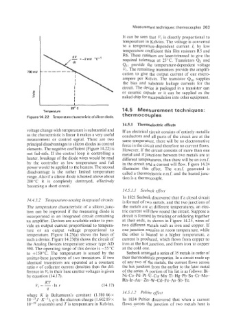
Figure14.22 Temperature characteristic of silicon diode. thermocouples
14.5.1 Thermoelectric effects
voltage change with temperature is substantial and If an electrical circuit consists of entirely metallic
as the characteristic is linear it makes a very useful conductors and all parts of the circuit are at the
measurement or control signal. There are two same temperature, there will be no electromotive
principal disadvantages to silicon diodes as control force in the circuit and therefore no current flows.
elements. The negative coefficient (Figure 14.22) is However, if the circuit consists of more than one
not fail-safe. If the control loop is controlling a metal and if junctions between two metals are at
heater, breakage of the diode wires would be read different temperatures, then there will be an emf.
by the controller as low temperature and full in the circuit and a current will flow. Figure 14.24
power would be applied to the heaters. The second illustrates this effect. The e.m.f. generated is
disadvantage is the rather limited temperature called a thermoelectric e.m.f. and the heated junc-
range. Also if a silicon diode is heated above about tion is a thermocouple.
200 "C it is completely destroyed, effectively
becoming a short circuit.
14.5.1.1 Seebeck effect
In 1821 Seebeck discovered that if a closed circuit
14.4.3.2 Tei7?perattire-sensirzg integrated circuits is formed of two metals, and the two junctions of
The temperature characteristic of a silicon junc- the metals are at different temperatures, an elec-
tion can be improved if the measuring diode is tric current will flow round the circuit. Suppose a
incorporated in an integrated circuit containing circuit is formed by twisting or soldering together
an amplifier. Devices are available either to pro- at their ends, as shown in Figure 14.25, wires of
vide an output current proportional to tempera- two different metals such as iron and copper. If
ture or an output voltage proportional to one junction remains at room temperature, while
temperature. Figure 14.23(a) shows the basis of the other is heated to a higher temperature, a
such a device. Figure 14.23(b) shows the circuit of current is produced, which flows from copper to
the Analog Devices temperature sensor type AD iron at the hot junction, and from iron to copper
590. The operating range of this device is -55 'C at the cold one.
to +150"C. The temperature is sensed by the Seebeck arranged a series of 35 metals in order of
emitter-base junctions of two transistors. If two their thermoelectric properties. In a circuit made up
identical transistors are operated at a constant of any two of the metals, the current flows across
ratio r of collector current densities then the dif- the hot junction from the earlier to the later metal
ference in V, in their base emitter voltages is given of the series. A portion of his list is as follows: Bi-
by equation (14.17). Ni-Co-Pd-Pt-U-Cu-Mn-Ti-Hg-PbSn-Cr-Mo-
Rh-Ir-Au- Zn-W-Cd-Fe-As-Sb-Te.
KT
V, = - 'In r (14.17)
4
14.5.1.2 Peltier effect
where K is Boltzmann's constant (1.380 66 x
10p'3J. Kpl), y is the electron charge (1.602 19 x In 1834 Peltier discovered that when a current
coulomb) and Tis temperature in Kelvins. flows across the junction of two metals heat is