
Page 282 - Instrumentation Reference Book 3E
P. 282
266 Temperature measurement
a cooler. The conductors and junctions have a big
cross-section to minimize IR heating. The warmer
face is clamped to a suitable heat sink while
the cold face has the component to be cooled
mounted in contact with it. Typical size for such
a unit is of the order of 5-25 mm. The conductors
in Peltier coolers may be either metals or semi-
conductors; in the latter case they are called Fri-
gistors.
14.5.1.3 Thonisoiz effect
Professor William Thomson (later Lord Kelvin) I I I
pointed out that if the reversible Peltier effect was fl Temperature t2 t"
the only source of e.m.f., it would follow that if
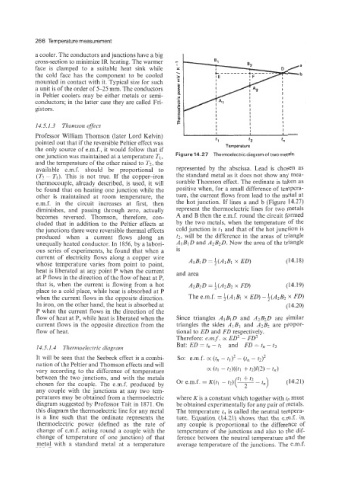
one junction was maintained at a temperature TI, Figure 14.27 Thermoelectric diagram of two metals.
and the temperature of the other raised to T2, the
available e.m.f. should be proportional to represented by the abscissa. Lead is chosen as
(T2 - TI). This is not true. If the copper-iron the standard metal as it does not show any mea-
thermocouple, already described, is used, it will surable Thomson effect. The ordinate is taken as
be found that on heating one junction while the positive when, for a small difference of tempera-
other is maintained at room temperature, the ture, the current flows from lead to the metal at
e.m.f. in the circuit increases at first, then the hot junction. If lines a and b (Figure 14.27)
diminishes, and passing through zero, actually represent the thermoelectric lines for two metals
becomes reversed. Thomson, therefore, con- A and B then the e.m.f. round the circuit formed
cluded that in addition to the Peltier effects at by the two metals, when the temperature of the
the junctions there were reversible thermal effects cold junction is tl and that of the hot junction is
produced when a current flows along an t2, will be the difference in the areas of triangle
unequally heated conductor. In 1856, by a labori- A1 B1 D and A2B2D. Now the area of the triangle
ous series of experiments, he found that when a is
current of electricity flows along a copper wire (14.18)
whose temperature varies from point to point,
heat is liberated at any point P when the current and area
at P flows in the direction of the flow of heat at P,
that is, when the current is flowing from a hot A2B2D = i(A2Bz x FD) (1 4.19)
place to a cold place, while heat is absorbed at P
when the current flows in the opposite direction. The e.m.f. = $(AIBI x ED) - k(A2Bz x FD)
In iron, on the other hand, the heat is absorbed at (14.20)
P when the current flows in the direction of the
flow of heat at P, while heat is liberated when the Since triangles AlBlD and A'BzD are similar
current flows in the opposite direction from the triangles the sides AlBl and A2B2 are propor-
flow of heat. tional to ED and FD respectively.
Therefore: emf. K ED' - FD'
14.5.1.4 Thermoelectric diagram But: ED = t, - tl and FD = t, - t2
It will be seen that the Seebeck effect is a combi- SO: e.m.f. K (t, - t1l2 - (ti, - t:> 2
nation of the Peltier and Thomson effects and will
vary according to the difference of temperature K (tl - fNtl + t2)42) - tn>
between the two junctions, and with the metals
chosen for the couple. The e.m.f. produced by
any couple with the junctions at any two tem-
peratures may be obtained from a thermoelectric where K is a constant which together with t, must
diagram suggested by Professor Tait in 1871. On be obtained experimentally for any pair of metals.
this diagram the thermoelectric line for any metal The temperature t,, is called the neutral tempera-
is a line such that the ordinate represents the ture. Equation (14.21) shows that the e.m.f. in
thermoelectric power (defined as the rate of any couple is proportional to the difference of
change of e.m.f. acting round a couple with the temperature of the junctions and also to the dif-
change of temperature of one junction) of that ference between the neutral temperature and the
metal with a standard metal at a temperature average temperature of the junctions. The e.m.f.