
Page 287 - Instrumentation Reference Book 3E
P. 287
Measurement techniques: thermocouples 271
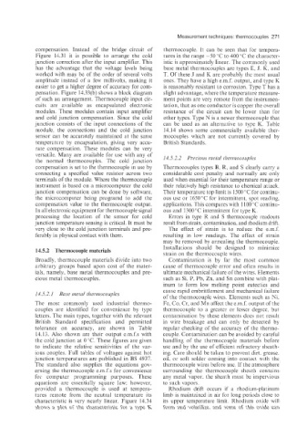
compensation. Instead of the bridge circuit of thermocouple. It can be seen that for tempera-
Figure 14.31 it is possible to arrange the cold tures in the range -50 "C to 400 "C the character-
junction correction after the input amplifier. This istic is approximately linear. The commonly used
has the advantage that the voltage levels being base metal thermocouples are types E, J. K, and
worked with may be of the order of several volts T. Of these J and K are probably the most usual
amplitude instead of a few millivolts, making it ones. They have a high e.m.f. output, and type K
easier to get a higher degree of accuracy for com- is reasonably resistant to corrosion. Type T has a
pensation. Figure 14.33(b) shows a block diagram slight advantage, where the temperature measure-
of such an arrangement. Thermocouple input cir- ment points are very remote from the instrumen-
cuits are available as encapsulated electronic tation, that as one conductor is copper the overall
modules. These modules contain input amplifier resistance of the circuit can be lower than for
and cold junction compensation. Siiice the cold other types. Type N is a newer thermocouple that
junction consists of the input connections of the can be used as an alternative to type K. Table
module, the coiinections and the cold junction 14.14 shows some commercially available thes-
sensor can be accurately maintained at the same mocouples which are not currently covered by
temperatnre by encapsulation, giving very accu- British Standards.
rate compensation. These modules can be very
versatile. Many are available for use with any of 14.5.2.2 Preciotts iuetal thernzocozyles
the normal thermocouples. The cold junction
compensation is set to the thermocouple in use by Thermocouples types B: R, and S clearly carry a
connecting a specified value resistor across two considerable cost penalty and normally are only
terminals of the module. Where the thermocouple used when essential for their temperature range or
instrument is based on a microcomputer the cold their relatively high resistance to chemical attack.
junction compensation can be done by software, Their temperature top limit is 1500 "C for continu-
the microcomputer being programd to add the ous use or 1650 "C for intermittent, spot reading,
compensation value to the thermocouple output. applications. This compares with 1100 "C continu-
In all electronic equipment for thermocouple signal ous and 1300°C intermittent for type K.
processing the location of the sensor for cold Errors in type R and S thermocouple readouts
junction temperature sensing is critical. It must be result from strain. Contamination, and rhodium drift.
very close to the cold junction terminals and pre- The effect of strain is to reduce the e.m.f.
ferably in physical contact with them. resulting in low readings. The effect of strain
may be removed by annealing the thermocouple.
Installations should be designed to minimize
14.5.2 Thermocouple materials
strain on the thermocouple wires.
Broadly, thermocouple materials divide into two Contamination is by far the most common
arbitrary groups based upon cost of the mater- cause of thermocouple error and often results in
ials, namely, base metal thermocouples and pre- ultimate mechanical failure of the wires. Elements
cious metal thermocouples. such as Si: P, Pb, Zn, and Sn combine with plat-
inum to form low melting point eutectics and
cause rapid embrittlemeiit and mechanical failure
14.5.2.1 Bme metal tlzermocozyles
of the thermocouple wires. Elements such as Ni.
The most coniionly used industrial thermo- Fe, Co, Cr, and Mn affect the e.m.f. output of the
couples are identified for convenience by type thermocouple to a greater or lesser degree, but
letters. The main types, together with the relevant contamination by these elements does not result
British Standard specification and permitted in wire breakage and can only be detected by
tolerance on accuracy, are shown in Table regular checking of the accuracy of the thermo-
14.13. Also shown are their output e.m.f.s with couple. Contamination can be avoided by careful
the cold junction at 0 "C. These figures are given handling of the thermocouple materials before
to indicate the relative sensitivities of the var- use and by the use of efficient refractory sheath-
ious couples. Full tables of voltages against hot ing. Care should be taken to prevent dirt. grease.
junction temperatures are published in BS 4937. oil, or soft solder coming into contact with the
The standard also supplies the equations gov- thermocouple wires before use. If the atmosphere
erning the thermocouple e.m.f.s for convenience surrounding the thermocouple sheath contains
for computer programming purposes. These any metal vapor, the sheath must be impervious
equations are essentially square law; however, to such vapors.
provided a thermocouple is used at tempera- Rhodium drift occurs if a rhodium-platinum
tures remote from the neutral temperature its limb is maintained in air for long periods close to
characteristic is very nearly linear. Figure 14.34 its upper temperature limit. Rhodium oxide will
shows a plot of the characteristic for a type K foim and volatilize, and some of this oxide can