
Page 285 - Instrumentation Reference Book 3E
P. 285
Measurement techniques: thermocouples 269
Stable power supply
Thermocouple ---
junction
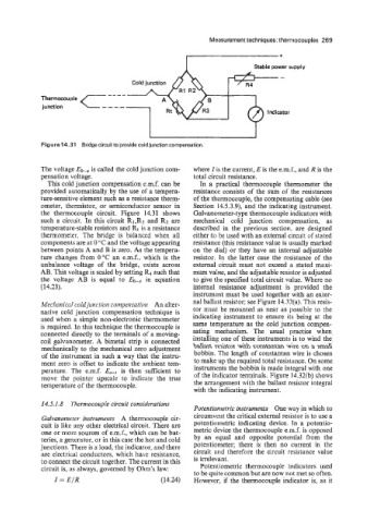
Figure 14.31 Bridge circuit to provide cold junction compensation.
The voltage EO-, is called the cold junction com- where I is the current, E is the e.m.f., and R is the
pensation voltage. total circuit resistance.
This cold junction compensation e.m.f. can be In a practical thermocouple thermometer the
provided automatically by the use of a tempera- resistance consists of the sum of the resistances
ture-sensitive element such as a resistance therm- of the thermocouple, the compensating cable (see
ometer, thermistor, or semiconductor sensor in Section 14.5.3.9), and the indicating instrument.
the thermocouple circuit. Figure 14.31 shows Galvanometer-type thermocouple indicators with
such a circuit. In this circuit R1,RZ and R3 are mechanical cold junction compensation, as
temperature-stable resistors and Rt is a resistance described in the previous section. are designed
thermometer. The bridge is balanced when all either to be used with an external circuit of stated
components are at 0 "C and the voltage appearing resistance (this resistance value is usually marked
between points A and B is zero. As the tempera- on the dial) or they have an internal adjustable
ture changes from 0°C an e.m.f., which is the resistor. In the latter case the resistance of the
unbalance voltage of the bridge, exists across external circuit must not exceed a stated maxi-
AB. This voltage is scaled by setting such that mum value, and the adjustable resistor is adjusted
the voltage AB is equal to EO-,). in equation to give the specified total circuit value. Where no
(14.33). internal resistance adjustment is provided the
instrument must be used together with an exter-
Meclzanical coldjiriiction corvipensatioiz An alter- nal ballast resistor; see Figure 14.32(a). This resis-
native cold junction compensation technique is tor must be mounted as near as possible to the
used when a simple non-electronic thermometer indicating instrument to ensure its being at the
is required. In this technique the thermocouple is same temperature as the cold junction compen-
connected directly to the terminals of a moving- sating mechanism. The usual practice when
coil galvanometer. A bimetal strip is connected installing one of these instruments is to wind the
mechanically to the mechanical zero adjustment ballast resistor with constantan wire on a small
of the instrument in such a way that the instru- bobbin. The length of constantan wire is chosen
ment zero is offset to indicate the ambient tem- to make up the required total resistance. On some
perature. The e.m.f. Et,+ is then sufficient to instruments the bobbin is made integral with one
move the pointer upscale to indicate the true of the indicator terminals. Figure 14.32(b) shows
temperature of the thermocouple. the arrangement with the ballast resistor integral
with the indicating instrument.
14.5.1.8 Thern.nlocouple circuit considerotions
Potentionietric instruments One way in which to
Gahanoineter instrunleiits A thermocouple cir- circumvent the critical external resistor is to use a
cuit is like any other electrical circuit. There are potentiometric indicating device. In a potentio-
one or nioi-e sources of e.m.f., which can be bat- metric device the thermocouple e.m.f. is opposed
teries, a generator, or in this case the hot and cold by an equal and opposite potential from the
junctions. There is a. load, the indicator, and there potentiometer; there is then no current in the
are electrical conductors, which have resistance, circuit and therefore the circuit resistance value
to connect the circuit together. The current in this is irrelevant.
circuit is, as always, governed by Ohm's law: Potentiometric thermocouple indicators used
to be quite common but are now not met so often.
I = E/R (14.24) However, if the thermocouple indicator is, as it