
Page 293 - Instrumentation Reference Book 3E
P. 293
Measurement techniques: thermocouples 277
cu
Readout
instrument \\\ ------- -
types
C.J. compensation /-
cable Pt
Cu:Ni
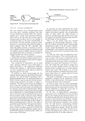
Figure 14.41 Thermocouple compensating cable
14.5.3. IO Accuracy consideration
In carrying out these calibrations the whole
The very extensive use of thermocouples stems installation needs to be calibrated: thermocouple
from their great versatility combined with their readout instrument together with compensating
low cost. However, as seen in Table 14.13, thermo- cable. In cases where very high accuracy is
couples have a fairly wide permitted tolerance. required, compensating cable should not be used;
This is due to the fact that most metals used for the conductors should be thermocouple metal for
thermocouples are alloys and it is not possible to the full length of the installation.
manufacture alloys to the same reproducibility as There is on the market some very versatile
pure metals, It must be said that, in general, manu- equipment for thermocouple calibration. Typic-
facturers do manufacture their thermocouples to ally, the facilities provided include thermocouple
better tolerance than BS 4937 demands. But, simulation for types E, J, K. R. S, and T. thermo-
where the highest accuracy is required, it is essen- couple output measurement with cold junction
tial to calibrate thermocouples on installation and compensation and resistance thermometer simu-
to recalibrate them at regular intervals to monitor lation. Tests can be static or dynamic using ramp
any deterioration due to corrosion or diffusion of functions.
foreign elements into the hot junction. As with any other type of temperature mea-
Where high accuracy is required it is necessary surement the location of the thermocouple junc-
to calibrate first the thermocouple readout instru- tions is critical. This is just as important for the
ment and then the thermocouple itself in conjunc- cold junction as for the hot junction. It must be
tion with the instrument. remembered that there may well be a temperature
The calibration of instruments can be done gradient over quite short distances in an instru-
with a precision millivolt source which injects a ment and unless the cold junction temperature
signal equivalent to the temperature difference sensor is in close thermal contact with the cold
between the ambient or cold junction tempera- junction itself a reading error of several degrees
ture and a temperature in the region in which the Celsius may result. This problem is at its worst
thermoccluple is to be used. with mains electricity powered measuring instru-
To calibrate or check thermocouples the hot ments where there is a certain amount of heat
junction must be kept at an accurately known tem- liberated by the power unit.
perature. This can be done by inserting it into a The point to remember is that it is not usually
heated isothermal block. An isothermal block is a adequate to measure the air temperature in the
block of metal: large compared with the thermo- vicinity of the cold junctions. The sensor should
couple being measured and made of copper or be in good thermal contact with them.
aluminum. The block has provision for heating it An obvious point, but one which surprisingly
and in some cases cooling. It is well insulated from often causes trouble, is the mismatch between the
the environment and is provided with suitable holes thermocouple and the measuring instrument. The
for inserting various sizes of thermocouple. Where obvious mismatch is using the wrong type of
not so high precision is required the thermocouple thermocouple or compensating cable.
can be immersed in a heated fluidized sand bath. In the case of galvanometric instruments
This consists of an open vessel fitted with a porous inaccuracies occur if sufficient care has not been
bottom (usually made of sintered metal). Heated taken in the winding of the make-up resistor or if
air is forced up through the bottom. The vessel is the thermocouple has been changed and the new
filled with carefully graded sand. With the air com- external circuit resistance not checked. Careless
ing up through it the sand behaves like a liquid. it location or make-up of the ballast resistor so that
takes up the temperature of the air. The sand is a one of the cold junction terminals is too remote
good heat transfer medium. The apparatus makes a from the cold junction compensating element
most convenient way of calibrating temperature causes variable errors of several degrees as the
probes. Where maximum accuracy is essential the ambient temperature changes. Where the ballast
thermocouple should be calibrated against one of resistor required is of a low value, 10 ohms or so,
the IPTS-68 secondary reference points. Table 14.5 the best arrangement may well be to use a coil of
shows some of the points. compensating cable of the right resistance.