
Page 297 - Instrumentation Reference Book 3E
P. 297
Measurement techniques: radiation thermometers 281
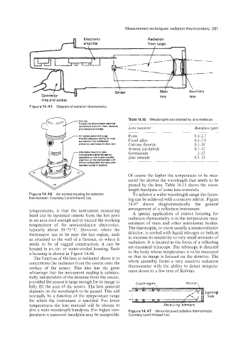
Radiation
_---
Main Auxiliary
lens lens
plug and socket
Figure 14.45 Diagram of radiation thermometer.
Table 14.15 Wavelengths transmitted by lens materials
Protern the thermomster eIcctricBI
connmtions from dirt, heat. moisture.
md mechanical damw Lens mateviol Bandpass (pm)
Air cooled jacket and purge. Pyrex 0.3-2.7
Providm sdquate MOling for -It Fused silica
applications. full mecSanical 0.3-3.8
protection, and keeps the lens clean Calcium fluoride 0.1-10
Arsenic trisulphide 0.7-12
Adjustable mounting Plate. Germanium 2-12
Incorwmtera wheriwl xating
adjustable on site to giw accurst0 Zinc selenide 0.5-!5
alignment of the thsrrmroem with
surface after tho main plate
n bolted in waition
Of course the higher the temperature to be mea-
sured the shorter the wavelength that needs to be
passed by the lens. Table 14.15 shows the wave-
length bandpass of some lens materials.
To achieve a wider wavelength range the focus-
thermometer. Courtesv Land infrared Ltd. ing can be achieved with a concave mirror. Figure
14.47 shows diagrammatically the general
temperatures, is that the instrument measuring arrangement of a reflection instrument.
head can be mounted remote from the hot zone A special application of mirror focusing for
in an area cool enough not to exceed the working radiation thermometry is in the temperature mea-
temperature of the semiconductor electronics. surement of stars and other astronomic bodies.
typically about 50-75 "C. However, where the The thermopile, or more usually a semiconductor
instrument has to be near the hot region, such detector, is cooled with liquid nitrogen or helium
as attached to the wall of a furnace, or where it to increase its sensitivity to very small amounts of
needs to be of rugged construction, it can be radiation. It is located at the focus of a reflecting
housed in an air- or water-cooled housing. Such astronomical telescope. The telescope is directed
a housing is shown in Figure 14.46. to the body whose temperature is to be measured
The function of the lens as indicated above is to so that its image is focused on the detector. The
concentrate the radiation from the source onto the whole assembly forms a very sensitive radiation
surface of the sensor. This also has the great thermometer with the ability to detect tempera-
advantage that the instrument reading is substan- tures down to a few tens of Kelvins.
tially independent of the distance from the source,
provided the source is large enough for its image to
ftilly fill the area of the sensor. The lens material
depends on the wavelength to be passed. This will Sighting
normally be a function of the temperature range hole
for which the instrument is specified. For lower
temperatures the lens material will be chosen to
give a wide wavelength bandpass. For higher tem- Figure 14.47 Mirror-focused radiation thermometer.
peratures a narrower bandpass may be acceptable. Courtesy Land Infrared Ltd.