
Page 364 - Instrumentation Reference Book 3E
P. 364
Electrical conductivity 347
The extent of polarization depends on a num- be of a high quality and not absorb anything
ber of factors, the most important of which are from the process liquid.
the nature of the electrode surface and the fre- A wide range of materials are at present avail-
quency of the a.c. signal applied to the cell. The able covering a wide range of pressures, tempera-
restrictions that polarization errors, arising from tures? and process fluids. The body may be made
electrode material, impose on the choice of cell of glass, epoxy resins, plastics such as PTFEI pure
mean that cells with bright metal electrodes are or reinforced, PVC, Perspex, or any othe, ,- mater-
best suited for measurements of low conductiv- ial suitable for the application, but it must not be
ities where the proportion of the total resistance deformed in use by temperature or pressure;
due to polarization is very small. Treated or otherwise, the cell constant will change.
coated electrodes are suitable for low The electrodes may be parallel flat plates or
(-0.05 pS cm-') to intermediate (-0.1s m-I) rings of metal or graphite cast in the tube forming
conductivities provided that the frequency of the the body, or in the form of a central rod with a
a.c. voltage is in the range normally found in concentric tubular body.
commercial instruments (50-1000 Hz). One common form of rod-and-tube conductiv-
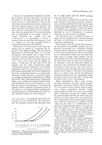
Polarization in all the cells we have been dis- ity cell consists of a satinized stainless steel rod-
cussing can be reduced by increasing the fre- electrode surrounded by a cylindrical stainless
quency of the applied voltage. This can best be steel electrode, having holes to permit the sample
appreciated by considering Figure 17.1 in which to flow freely through the cell. This is surrounded
the apparent cell constant over a range of con- by an intermediate cylinder also provided with
ductivities is plotted against three values of a.c. holes, and two O-rings which together with the
frequency. The true value of the cell constant was tapered inner end form a pressure-tight seal onto
1 cm-' and it can be seen that the highest fre- the outer body when the inner cell is withdrawn
quency, 3.5 kHz, gave the true value for the cell for cleaning, so that the measured solution can
constant over the widest concentration range. continue to flow and the cell be replaced without
Unfortunately increase of frequency can introduce interruption of the process. The outer body is
capacitative errors into the measurement, particu- screwed into the line through which the measured
larly from the signal cable, and in many applications solution flows. Figure 17.2(a) shows the inserted
the choice of operating frequency is a compromise. cell as it is when in use, and (b) the withdrawn
Although variable frequency conductivity meters measuring element with the intermediate sleeve
are available as laboratory instruments (e.g., Philips forming a seal on the outer body. The cell may
Model PW 9509, High Performance Conductivity be used at 110°C up to 7 bar pressure.
Meter), suich a facility is not usually found on indus- Many manufacturers offer a type of flow-
trial instruments. In this case it is necessary to con- through conductivity cell with annular graphite
sider the range of conductivities to be measured, electrodes, one form of which is shown in Figure
together with the chemical and physical nature of 17.3. It consists of three annular rings of imper-
the solutions to be measured before specifying the vious carbon composition material equally
operating frequency. All determinations of cell con- spaced within the bore of an epoxy resin molded
stant should be carried out at this frequency. body. Conduction through the solution within
the cell takes place between the central electrode
and the two outer rings, which are connected to
Cell construction The materials used in cell con- the earthed terminal of the measuring instrument;
struction must be unaffected by the electrolyte, thus, electrical conduction is confined entirely
and the insulation between the electrodes must within the cell, where it is uninfluenced by the
presence of adjoining metal parts in the pipe sys-
1.40 r f lHrl 50 500 tem. This pattern of cell, having a simple flow
/
path, is ideally suited to the exacting require-
ments of dialysate concentration monitoring in
the artificial kidney machine. Screw-in patterns
of this cell are also generally available.
The use of an impervious carbon composition
material for the electrodes substantially elimin-
ates polarization error and provides conducting
IrnS i Crn) -
surfaces that do not require replatinization or
10 20 50 100 200 500 1 2 5 10 20 50 1W 2W 500 1000 special maintenance, other than periodic, but
-ips I Crnl simple and infrequent cleaning by means of a
Solution canductiulTy k bottle brush. Typical operating temperature and
Figurel7.1 Effectoffrequencyon theuseful rangeofa pressure limits for this type of cell are 100 "C and
cell with titanium carbide coated stainless steel electrodes.
Courtesy F. Oehme, Polymetron. 7 bar.