
Page 368 - Instrumentation Reference Book 3E
P. 368
Electrical conductivity 351
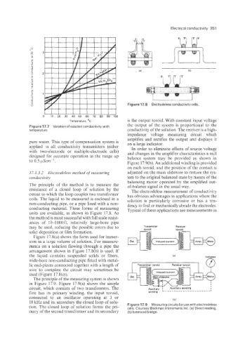
Figure 17.8 Electrodeless conductivity cells.
Temperature, ‘C is the output toroid. With constant input voltage
Figure 17.7 Variation of solution conductivity with the output of the system is proportional to the
temperature. conductivity of the solution. The receiver is a high-
impedance voltage measuring circuit which
amplifies and rectifies the output and displays it
pure water. This type of compensation system is on a large indicator.
applied m all conductivity transmitters (either In order to eliminate effects of source voltage
with two-electrode or multiple-electrode cells) and changes in the amplifier characteristics a null
designed for accurate operation in the range up balance system may be provided as shown in
to 0.5 LLscun-l.
Figure 17.9(b). An additional winding is provided
on each toroid, and the position of the contact is
17.3.3.2 Electrodeless method of measuring adjusted on the main slidewire to restore the sys-
Conductivity tem to the original balanced state by means of the
balancing motor operated by the amplified out-
The principle of the method is to measure the of-balance signal in the usual way.
resistance of a closed loop of solution by the The electrodeless measurement of conductivity
extent to which the loop couples two transformer has obvious advantages in applications where the
coils. The liquid to be measured is enclosed in a solution is particularly corrosive or has a ten-
non-conducting pipe, or a pipe lined with a non- dency to foul or mechanically abrade the electrodes.
conducting material. Three forms of measuring Typical of these applications are measurements in
units are available, as shown in Figure 17.8. As
the method is most successful with full scale resist-
ances of 10-1000 R; relatively large-bore pipe
may be used, reducing the possible errors due to Transmitter toroid
Receiver
... -
solid deposition or film formation. 6ii
Figure 17.8(a) shows the form used for immer-
sion in a iarge volume of solution. For measure-
ments on a solution flowing through a pipe the
arrangement shown in Figure 17.8(b) is used. If
the liquid contains suspended solids or fibers,
wide-bore -non-conducting pipe fitted with metal-
lic end-pieces connected together with a length of
wire to complete the circuit may sometimes be
used (Figure 17.8(c)).
The principle of the measuring system is shown
in Figure 17.9. Figure 17.9(a) shows the simple
circuit, which consists of two transformers. The
first has its primary winding, the input toroid,
connected to an oscillator operating at 3 or
18 kHz and its secondary the closed loop of solu- I bi
Figure 17.9 Measuring circuitsfor usewith electrodeless
tion. The closed loop of solution forms the pri- cells. Courtesy Beckman Instruments Inc. (a) Direct reading,
mary of the second transformer and its secondary (b) balanced bridge.