
Page 371 - Instrumentation Reference Book 3E
P. 371
354 Chemical analysis: electrochemical techniques
where chromatographic separation of either the peak and the area under the peak is a measure of
cations (+ve) or anions (-ve), depending on the the concentration of the ionic species giving rise
nature of the exchanger, takes place. The ion to it. In many cases peak heights rather than
exchange material in these chromatographic areas can be used as the indicator of concentra-
separator columns is fundamentally the same as tion, thus simplifying the measurement since an
conventional ion exchange resins but the integrator is not required. For most purposes this
exchange sites are limited to the surface of very is adequate since sharp elution peaks are obtained
fine resin beads. This form of exchanger has been by keeping mixing to a minimum by use of very
shown to have the characteristics required for narrow bore transmission tubing combined with
rapid separation and elution of the ionic compon- a conductivity cell whose volume is of the order
ents in the order expected from the general rules of 6 pZ. In cells of this size polarization resistance
of ion exchange (e.g., C1-’ before Br-’ before can be considerable due to the proximity of the
SO:-). At this stage the conductivity can be moni- electrodes.
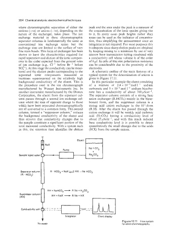
tored and the elution peaks corresponding to the A schematic outline of the main features of a
separated ionic components measured as typical system for the determination of anions is
increases superimposed on the relatively high given in Figure 17.11.
background conductivity of the eluent. This is In this particular example the eluent consisting
the procedure used in the ion chromatograph of a mixture of 2.4 x 10⁻³mol 1-’ sodium
manufactured by Wescan Instruments Inc. In carbonate and 3 x mol 1-’ sodium bicarbo-
another instrument manufactured by the Dionex nate has a conductivity of about 700 pscir-’.
Corporation, the eluent from the separator col- The separator column consists of a strong base
umn passes through a second ion exchange col- anion exchanger (R.HC03) mainly in the bicar-
umn where the ions of opposite charge to those bonate form, and the suppressor column is a
which have been separated chromatographically strong acid cation exchanger in the H+-form
are all converted to a common form. This second (R.H). After the eluent has passed through the
column, termed a “suppressor column,” reduces cation exchange it will be weakly acid carbonic
the background conductivity of the eluent and acid (H2C03) having a conductivity level of
thus ensures that conductivity changes due to about 25pScm-l, and with this much reduced
the sample constitute a significant portion of the base conductivity level it is possible to detect
total measured conductivity. With a system such quantitatively the small changes due to the acids
as this, the retention time identifies the elution (H.X) from the sample anions.
Eluent
NaX
Na + CO,
Pump +
Sample inject valve - I t Na2C0,
i
R
Na
Suppressor column RH + NaHCO, - + H2C0,
RH+NaX - RNa+HX
(RH)
-
-
-
-
-
Conductivity cell ----- - __ - ~ o r ~ : : : ~ l
~
Figure17.11 Flowsystem
To waste Integrator Chart display for anion chromatography.