
Page 540 - Instrumentation Reference Book 3E
P. 540
Detectors 523
ters are used in radiocarbon dating systems
because of their sensitivity for the detection of low-
energj I4C beta particles (E,,,, = 156keV) and
even tritium 3H beta particles (E,,,,, = 18 keV).
22.2.1.1 Geiger-Mueller detectors High voltage -
v
The Geiger counter has been and is the most
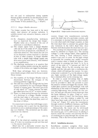
widely used detector of nuclear radiation. It Figure 22.2 Geiger counter characteristic response
exhibits several very attractive features, some of
which are: sources. Geiger tube manufacturers normaily
quote the dead time of a particular counter, and
(1) Its cheapness-manufacturing techniques it is customary to increase this time electronically
have so improved the design that Geiger-
Mueller tubes are a fraction of the cost of in a unit often used with Geiger counters, so that
solid-state or scintillation detectors. the total dead time is constant but greater than
(2) The output signal froin a Geiger-Mueller any variations in the tube’s dead time, since
between individual pulses the dead time can vary.
tube can be of the order of 1 V, much higher
than that from proportional, scintillation, or The counting rate characteristics can be under-
solid-state detectors. This means that the cost stood by reference to Figure 22.2. The starting
voltage V, is the voltage which, when applied to
of the electronic system required is a fraction
of that of other counters. A Geiger-Mueller the tube viewing a fixed radioactive source,
tube with a simple high-voltage supply can makes it just start to count. As the high voltage
drive most scaler units directly, with minimal is increased the counting rate rapidly increases
or no amplification. until it reaches what is called the plateau. Here
(3 The discharge mechanism is so sensitive that the increase in counting rate from VA to VB is
small, of the order of 1-5 percent per lOOV of
a single ionizing particle entering the sensitive
volume of the counter can trigger the discharge. high voltage. Above VB the counting rate rises
rapidly and the tube goes into a continuous dis-
Nith these advantages there are, however, charge, which will damage the counter. An oper-
some disadvantages which must be borne in mind. ating point is selected ( VOp) on the plateau so that
These include: any slight variation of the high-voltage supply
has a minimal effect on the counting rate.
(1) The inability of the Geiger-Mueller tube to In order to count low-energy beta or alpha
discriminate between the energies of the particles with a Geiger counter a thin window
ionizing particles triggering it.
(2) The tube has a finite life, though this has been must be provided to allow the particles to enter
the sensitive volume and trigger the counter. Thin-
greatly extended bv the use of halogen fillings walled glass counters can be produced, with wail
instead of organic gases. The latter gave lives thicknesses of the order of 30 mg/cm2, suitable for
of only about 10’” counts whereas the halo- counting high-energy beta particles (in this con-
gen tubes have lives of lOI3 or more counts.
(3) Tlhere is a finite period between the initiation text, the mass per unit area is more import$nt than
the linear thickness: for glass, 25mg cm’ corie-
of a discharge in a Geiger-Mueller counter sponds to about 0.1 mm). For low-energy betas
and the time when it will accept a new dis- or alphas a very thin window is called for, and
charge. This is called the dead time, and is of these have been made with thicknesses as low as
the order of 100 ,us.
1.5 mg cm2. Figure 22.3 gives the transmission
It is important to ensure that with Geiger count- through windows of different thickness, and Table
ers the counting rate is such that the dead-time 22.4 show how it is applied to typical sources.
correction is only a small percentage of the count- Alternatively, the source can be introduced
ing rate observed. This correction can be calcu- directly into the counter by mixing as a gas with
Iated from the relation: the counting gas, or if a solid source, by placing it
directly inside the counter and allowing the flow
R
R’ = - (22.12) of counting gas to pass through the counter con-
i - RT tinuously. This is the flow-counter method.
where R is the observed counting rate per unit
time, R’ is the true counting rate per unit time and
T is the counter dead time. 22.2.2 Scintillation detectors
Dead time for a particular counter may be Scintillation counters comprise three main
evaluated by a series of measurements using two items: the scintillator, the light-to-electrical pulse