
Page 70 - Instrumentation Reference Book 3E
P. 70
Derived measurements 55
itself. The same concept is often applied using mul-
tiple electronic sensors placed in line or by stepping
a fixed interval along the whole distance, counting
the number of coarse intervals, and subdividing the
last partial interval by some other sensor that has
finer sensing detail.
When a non-contacting sensor is used (see
Figure 3.3), the length measurement is made by
a method that does not mechanically contact the
subject. An example is the use of an optical inter-
ferometer to monitor position of a machine slide.
It does not impose significant force on the slide
and, as such. does not alter the measured value by
its presence.
Contacting methods must be used with some
caution lest they alter the measurement value due
to the mechanical forces imposed by their pre-
sence.
.3 Derived measurements
3.3.1 Derived from length measurement alone
Length (m) comes into other measurement par-
ameters, including relative length change (mlm),
area (m2>, volume (m3), angle (dm), velocity X J
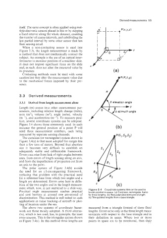
(m-'), and acceleration (m-*). To measure posi-
tion, several coordinate systems can be adopted.
Figure 3.4 shows those commonly used. In each
instance the general position of a point P will
need three measurement numbers, each being
measured by separate sensing channels.
The Cartesian (or rectangular) system shown in
Figure 3.4(a) is that most adopted for ranges less
than a few tens of meters. Beyond that absolute
size it becomes very difficult to establish an
adequately stable and calibratable framework.
Errors cain arise from lack of right angles between
axes, from errors of length sensing along an axis.
and from the imperfection of projection out from
an axis to the point.
The polar system of Figure 3.4(b) avoids
the need for an all-encompassing framework,
replacing that problem with the practical need
for a reference base from which two angles and a
length are determined. Errors arise here in defin-
ition of the two angles and in the length measure- C (c)
ment which, now, is not restricted to a slide-way. Figure 3.4 Coordinate systems that can be used to
Practical angle measurement reaches practical locate position in space. (a) Cartesian, rectangular, frame
and cost barriers at around one arc-second of for three lengths. (b) Two polar directions and a length.
discrimination. This method is well suited to such (c) Triangulated lengths from a base triangle.
applications as radar tracking of aircraft or plot-
ting of location under the sea.
The above two systems of coordinate frame- measured from a triangle formed of three fixed
work are those mostly adopted. A third alterna- lengths. Errors arise only in the three length meas-
tive. which is less used, has, in principle, the least urements with respect to the base triangle and in
error sources. This is the triangular system shown their definition in space. Where two or more
as Figure 3.4(c). In this method three lengths are points in space are to be monitored, then their