
Page 74 - Instrumentation Reference Book 3E
P. 74
Practice of length measurement for industrial use 59
porating manually or automatically read optical
scales. Figure 3.7 shows the modern form of such
measuring machines. This is capable of a guaran-
teed accuracy of around 1 pm in length measure-
ments up to its full range capability of 300mm.
Larger machines are also made covering the
range of around 4m: these machines have also
been adapted to provide electronic readout; see
Section 3.6.
Where measurement of complex shapes is
important, the use of measuring machines can
be quite tedious; more speedy, direct methods
can be used when the accuracy needed is not of
the highest limits. In this aspect of tool-room
measurement the optical profile projector may
be applicable.
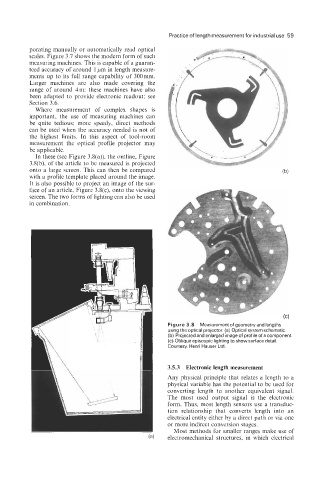
In these (see Figure 3.8(a)), the outline, Figure
3.8(b), of the article to be measured is projected
onto a large screen. This can then be compared
with a profile template placed around the image.
It is also possible to project an image of the sur-
face of an article, Figure 3.8(c), onto the viewing
screen. The two forms of lighting can also be used
in combination.
Figure 3.8 Measurement of geometryand lengths
using the optical projector. (a) Optical system schematic.
(b) Projected and enlarged image of profile of a component.
(c) Oblique episcopic lighting to show surface detail.
Courtesy, Henri Hauser Ltd.
3.5.3 Electronic length measurement
Any physical principle that relates a length to a
physical variable has the potential to be used for
converting length to another equivalent signal.
The most used output signal is the electronic
form. Thus, most length sensors use a transduc-
tion relationship that converts length into an
electrical entity either by a direct path or via one
or more indirect conversion stages.
Most methods for smaller ranges make use of
electromechanical structures, in which electrical