
Page 77 - Instrumentation Reference Book 3E
P. 77
62 Measurement of length
without need for separate electronic excitation. It the null position, the output will be an a.c. signal
will not, however, produce a distance measure- of the excitation frequency which changes in
ment when the system is stationary unless excited amplitude with position and having direction in
by a continuous a.c. carrier signal. the signal as its phase.
Where possible two similar variable-reluctance Practical use generally requires a d.c. output
units are preferred, mounted on each side of the signal (actually a signal having frequency compon-
moving object, and connected into a bridge con- ents in it that are present in the measured value's
figuration giving common-mode rejection of movement) with direction information as signal
unwanted induced noise pick-up. These arrange- polarity. This is easily achieved, at marginal addi-
ments are but two of many possible forms that tional expense, by the use of phase-sensitive
have been applied. Variable-reluctance methods detection (also known as lock-in detection or
are characterized by their relatively short range, carrier demodulation). Figure 3.13(a) shows a
poor linearity over longer ranges, and the possible block diagram of the subsystem elements that
need to move a considerable mass in making the form a complete LVDT length-measuring system.
measurement with consequent restricted dynamic Figure 3.13(b) shows the output relationship
performance. with position of the core. Modern units now often
Mutual-inductance methods also exist in very supply the phase-sensitive detection circuits inside
many forms including the equivalent of Figure the case of the sensor; these are known as d.c.
3.11. Probably the most used is the linear vari- LVDT units. Considerable detail of the operation
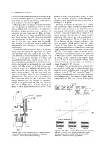
able-differential transformer (LVDT). Figure 3.12 of these and variations on the theme are available
shows a cross-section through a typical unit in Herceg (1976). Detail of phase-sensitive detec-
mounted for monitoring length change of a ten- tion is in Part 4 and Sydenham (1982b), where
sile test specimen. A magnetic material core, nor- further references will be found in a chapter on
mally a ferrite rod, moves inside three coils placed signal detection by D. Mnnroe.
end to end. The center coil is fed from an a.c. A simpler non-transformer form of the LVDT
excitation supply thus inducing voltages into the arrangement can be used in which the need for a
outer two coils. (It can also be wound over the separate central excitation coil is avoided. With
other two outer coils.) The two generated vol- reference to the LVDT unit shown in Figure 3.12
tages will be equal when the core is positioned the two outer coils only would be used, their inner
symmetrically. The voltage rises in one coil rela- ends being joined to form a center-tapped linearly
tive to the other when the core is off-center. Dif- wound inductor. This split inductor is then placed
ference between the two voltages is, therefore,
related to the position of the core, and the rela-
tion can be made linear. Without circuitry to
detect in which direction the core has moved from
Voltageout. oppoiite phase t 1
-
adjust
w
L,?1 'Zero Core at A Core at ""I1 Core at 8
Figure 3.13 Phase-sensitive detection system used with
Figure 3.12 Cross-section of an LVDTinductive length practical LVDTs. (a) Block diagram of electronic system.
sensor used to measure length change of a tensile test (b) Input-output characteristics after phase-sensitive
specimen. Courtesy Schaevitz Engineering. detection. Courtesy Schaevitz Engineering.