
Page 80 - Instrumentation Reference Book 3E
P. 80
Practice of length measurement for industrial use 65
cases the so-called Wallmark or lateral effect cell,
Figure 3.15(b), may be more appropriate. In this
case the two contacts are not rectifying as in the
Figure 3.15(a) case but are, instead, ohmic.
Uniform illumination It has been shown thst the voltage produced
beam lrhown in null polltion/
between the two ohmic contacts is related to the
position of the centroid of the beam's energy and
(a)
to the intensity of the whole beam. Addition of
p-n IlIlCml the rectifying contact on the other side of the cell
photocells mounted
adiacenily Of beam enables correction to be made for intensity
changes, making this form of cell able to track
the movements of a spot of radiation that
changes both intensity and in size. Here also the
Elect beam must be smaller than the full working
ear-mounted ohmic contacts region of the cell surface. Detection limits are
similar to those of the split cell form.
(b) This cell has enjoyed a resurgence of interest
in its design, for the original logarithmic voltage-
f movement of beam
to-position characteristic can quite easily be
Front mounted arranged to be effectively linear by driving the
ohmic contact for
~nten~y compensation cell into the appropriate impedance amplifier. It,
too, is able to sense the motion of a beam in two
axes simultaneously by the use of two additional
contacts placed at right angles to those shown.
Optical position-sensitive photocells, such as
these, have found extensive use in conjunction
with laser sources of radiation in order to align
floors, ceilings, and pipes and to make precise
mechanical measurement of geometry deviations
in mechanical structures.
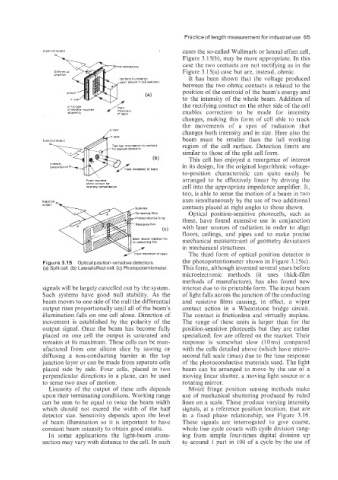
The third form of optical position detector is
Figure 3.15 Optical position-sensitive detectors. the photopotentiometer shown in Figure 3.P5(c).
(a) Split cell. (b) Lateral effect cell. (c) Photopotentiorneter. This form, although invented several years before
microelectronic methods (it uses thick-film
methods of manufacture), has also found new
signals will be largely cancelled out by the system. interest due to its printable form. The input beam
Such systems have good null stability. As the of light falls across the junction of the conducting
beam moves to one side of the null the differential and resistive films causing, in effect, a wiper
output rises proportionally until all of the beam's contact action in a Wheatstone bridge circuit.
illumination falls on one cell alone. Direction of The contact is frictionless and virtually stepless.
movement is established by the polarity of the The range of these units is larger than for the
output signal. Once the beam has become fully position-sensitive photocells but they are rather
placed on one cell the output is saturated and specialized; few are offered on the market. Their
remains at its maximum. These cells can be man- response is somewhat slow (10 ms) compared
afactured from one silicon slice by sawing or with the cells detailed above (which have micro-
diffusing a non-conducting barrier in the top second full scale times) due to the time response
junction layer or can he made from separate cells of the photoconductive materials used. The light
placed side by side. Four cells, placed in two beam can be arranged to move by the use of a
perpendicular directions in a plane, can be used moving linear shutter, a moving light source or a
to sense two axes of motion. rotating mirror.
Linearity of the output of these cells depends Moire fringe position sensing methods make
upon their terminating conditions. Working range use of mechanical shuttering produced by ruled
can be seen to he equal to twice the beam width lines on a scale. These produce varying intensity
which should not exceed the width of the half signals, at a reference position location. that are
detector size. Sensitivity depends upon the level in a fixed phase relationship; see Figure 3.16.
of beam illumination so it is important to have These signals are interrogated to give coarse,
constant beam intensity to obtain good results. whole line cycle counts with cycle division rang-
In same applications the light-beam cross- ing from simple four-times digital division up
section may vary with distance to the cell. In such to around 1 part in 100 of a cycle by the use of