
Page 84 - Instrumentation Reference Book 3E
P. 84
Automatic gauging systems 69
representing one or many length dimensions.
In simple applications the operator places the
component in a preset, multiprobe system. In
a totally automated plant use is often made of
pick-and-place robots to load the inspection
machines.
Automatic inspection systems began their
development in the 1950s when they were
required to complement the then emerging
numerically controlled metal-working machine
tools. They made use of similar measuring sen-
sors as did the tools but differed from the metal
working machine in several ways.
Where inspection machines are hand-operated
the operator can work best when the system effect-
ively presents no significant inertial forces to the
input probe as it is moved. This can be achieved
by a design that minimizes the moving masses or
by the use of closed-loop sensor control that
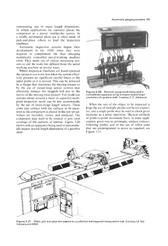
effectively reduces the sluggish feel due to the Figure 3.20 Electronic gauge heads being used in
inertia of the moving mass present. For small-size a versatile test apparatus set up to inspect several length
systems (those around a meter in capacity) multi- parameters of a gearbox shaft. Courtesy, C. E. Johansson.
point inspection needs can be met economically
by the use of short-range length sensors. These When the size of the object to be inspected is
come into contact with the surfaces to be meas- large the use of multiple probes can be too expens-
ured as the component is placed in the test set-up. ive, and a single probe may be used to check given
Values are recorded, stored, and analyzed. The locations as a serial operation. Manual methods
component may need to be rotated to give total of point-to-point movement have, in some appli-
coverage of the surfaces of interest. Figure 3.20 cations, given way to automatic, surface contour-
shows such an apparatus being used to automatic- following probes and to the use of robot arms
ally inspect several length dimensions of a gearbox that are preprogramed to move as required; see
shaft. Figure 3.21.
Figure 3.21 Robot, pick-and-place arm adapted to a production-line inspection measurement task. Courtesy, LK Tool
Company and ASEA.