
Page 81 - Instrumentation Reference Book 3E
P. 81
66 Measurement of length
The position of the spots can be sensed with a
position-sensitive photocell as described above.
Where digital output of beam movement is
neni of needed it is also possible to use a linear array of
photodetectors each operating its own level detec-
tor or being scanned, sequentially, into a single
output channel. Linear arrays with over 200 elem-
ents are now commonplace.
Photo detector array Optical lenses and mirrors can be used to alter
produces phased signals
as maire'trinaesrnove in the beam movement geometry in order to scale
vertical direction
lor horizontal according
ta choice of index and the subject's movement amplitude to suit that of
reference frame I scale)
an optical position detector.
3.5.4.2 Interferometyy and transit-time methods
source of
radiation
lliurnlnaring Where long length (meters and above) measure-
grating and
index ments are needed it is possible to use a suitable
Figure 3.1 6 Moirhfringes used to measure length beam of radiation sensed in its longitudinal direc-
tion. Several different methods are available.
analog subdivision methods. Moire fringe scales If the beam has time-coherent properties
are able to provide large range (by butting sec- (either superimposed or inherently in the carrier)
tions) and a discrimination level at the subdivi- it will then be possible to use interference methods
sion chosen which can be as small as lpm. to detect phase differences between a reference
Accuracy is limited by the placement of the lines part of the beam and that sent to the subject to
on the scale, by the mounting of the scale, and by be reflected back. Laser, microwave sources, and
the temperature effects that alter its length. The coherently generated acoustic radiation each can
method is suitable for both linear and rotary be used in this interference mode. The shorter
forms of sensing. the wavelength of the radiation, the smaller the
Although there was much developmental activ- potential discrimination that can be obtained.
ity in moirC methods in the 1950-to-1965 period, Thus with optical interferometers it is practical
their design has stabilized now that the practical- to detect length differences as small as a nano-
ities have been realized. meter but only around a few millimeters when
MoirC methods have also found use for strain microwave radiation is used.
investigation, a subject discussed in Chapter 4. Figure 3.18 shows the basic layout of the
The easily procured coherent properties of con- optical elements needed to form a laser-based
tinuous wave laser radiation have provided a sim- interferometer. That shown incorporates fre-
ple, yet highly effective method for monitoring quency stabilization and Zeeman splitting of the
the diameter of small objects such as wire as it is radiation features that give the system a highly
being drawn. The radiation, being coherent, dif- stable and accurate measurement capability and a
fracts at the intersection with the wire producing frequency, rather than amplitude form, of output
a number of diffraction beams at points past the representing length. A commercial unit is shown
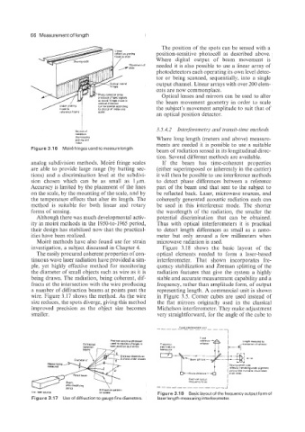
wire. Figure 3.17 shows the method. As the wire in Figure 3.5. Corner cubes are used instead of
size reduces, the spots diverge, giving this method the flat mirrors originally used in the classical
improved precision as the object size becomes Michelson interferometer. They make adjustment
smaller. very straightforward, for the angle of the cube to
srea-modifying
OPflCS
Pattern
Figure 3.18 Basiclayoutof thefrequencyoutputformof
Figure 3.17 Use of diffraction to gauge fine diameters. laser length-measuring interferometer.