
Page 76 - Instrumentation Reference Book 3E
P. 76
Practice of length measurement for industrial use 61
alternative inductive and capacitive methods; the Interroyatio~
impedance of a resistance unit set to give fine
discrimination generally is required to be high
with subsequent inherent resistance noise gener-
ation. These units are variously described in most
general instrumentation texts. The alternative
method, Figure 3.9(b), makes use of strain of
the bulk properties of the resistance, the most (3)
used method being the resistance strain gauge. Induction depends on
number of turns
As strain gauges are the subject of Chapter 4 they
will not be discussed further at this stage.
An alternative bulk resistance method that
sometimes has application is to use a material,
such as carbon in disc form, using the input
length change to alter the force of surface contact
between the discs. This alters the pile resistance.
The method requires considerable force from the
input and, therefore, has restricted application. It ( b)
does, however, have high electric current-carrying
capability and can often be used to drive directly Input
quite powerful control circuits without the need
for electronic amplification. The bulk properties 'rogation CilCUlfry
method can only transduce small relative length
changes of an interval. Practical reasons generally
restrict its use to gauge intervals of a few milli- VsrVlny COupliny
meters and to strains of that interval of around 1 between coils
percent.
armatUre (C)
3.5.3.2 Electrical magnetic inductive processes in coils
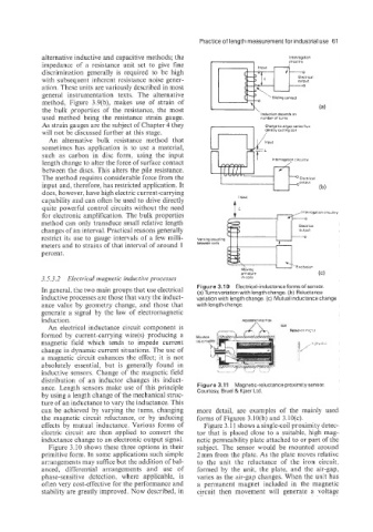
Figure 3.1 0 Electrical-inductance forms of sensor.
In general, the two main groups that use electrical (a) Turnsvariation with length change. (b) Reluctance
inductive processes are those that vary the induct- variation with length change. (c) Mutual inductance change
ance value by geometry change, and those that with length change.
generate a signal by the law of electromagnetic
induction.
An electrical inductance circuit component is
formed by current-carrying wire(s) producing a
magnetic field which tends to impede current
change in dynamic current situations. The use of
a magnetic circuit enhances the effect; it is not
absolutely essential, but is generally found in
inductive sensors. Change of the magnetic field
distribution of an inductor changes its induct-
ance. Length sensors make use of this principle Figure 3.11 Magnetic-reluctance proximity sensor.
Courtesy, Bruel & Kjaer Ltd.
by using a. length change of the mechanical struc-
ture of an inductance to vary the inductance. This
can be achieved by varying the turns, changing more detail, are examples of the mainly used
the magnetic circuit reluctance, or by inducing forms of Figures 3.10(b) and 3.10(c).
effects by mutual inductance. Various forms of Figure 3.11 shows a single-coil proximity detec-
electric circuit are then applied to convert the tor that is placed close to a suitable, high mag-
inductance change to an electronic output signal. netic permeability plate attached to or part of the
Figure 3.10 shows these three options in their subject. The sensor would be mounted around
primitive form. In some applications such simple 2 mm from the plate. As the plate moves relative
arrangements may suffice but the addition of bal- to the unit the reluctance of the iron circuit;
anced, differential arrangements and use of formed by the unit, the plate, and the air-gap,
phase-sensitive detection, where applicable, is varies as the air-gap changes. When the unit has
often very cost-effective for the performance and a permanent magnet included in the magnetic
stability are greatly improved. Now described, in circuit then movement will generate a voltage