
Page 75 - Instrumentation Reference Book 3E
P. 75
60 Measurement of length
resistance, inductance, or capacitance vary, or R1 + R:, = a resistance p-
make use of time and spatial properties of radia- 1
tion. Basic cells of such units are often combined
to form larger range devices having similar dis- of L length
crimination and dynamic range to those given by c/.---
the best mechanical measuring machines. vs
For best results differential methods are util- Supply voltage
dc or ac
ized where practicable for this reduces the inher-
ent errors (no transducers are perfect!) of the = -. R1 V, (if R1 not loaded electrically1
R1+ R2
various systems by providing an in-built mechan- -;
- -.
ism that compensates for some deficiencies of the "5
transducer principle adopted. For example, to (a)
measure displacement it is possible to use two
electrical plates forming a capacitor. As their
separation varies, the capacitance alters to give Hc---f-
6L
a corresponding change in electrical signal. To
use only one plate-pair makes the system directly -4 R
susceptible to variations in the dielectric constant Applied force
of the material between the plates; small changes V,,,oALmAR
in the moisture content in an air-gap can give rise (b)
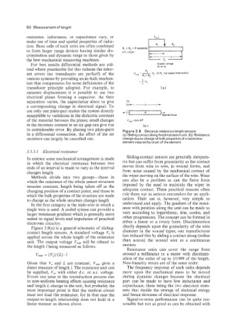
to considerable error. By placing two plate-pairs Figure 3.9 Electrical-resistance length sensors.
in a differential connection, the effect of the air (a) Sliding contact along fixed resistance unit. (b) Resistance
moisture can largely be cancelled out. change due to change of bulk properties of a resistance
element induced by strain of the element.
3.5.3.1 Electrical resistance
In essence some mechanical arrangement is made Sliding-contact sensors are generally inexpens-
in which the electrical resistance between two ive but can suffer from granularity as the contact
ends of an interval is made to vary as the interval moves from wire to wire, in wound forms, and
changes length. from noise caused by the mechanical contact of
Methods divide into two groups-those in the wiper moving on the surface of the wire. Wear
which the resistance of the whole sensor structure can also be a problem as can the finite force
remains constant, length being taken off as the imposed by the need to maintain the wiper in
changing position of a contact point, and those in adequate contact. These practical reasons often
which the bulk properties of the structure are made rule them out as serious contenders for an appli-
to change as the whole structure changes length. cation. Their use is, however, very simple to
In the first category is the slide-wire in which a understand and apply. The gradient of the resist-
single wire is used. A coiled system can provide a ance with position along the unit can be made to
larger resistance gradient which is generally more vary according to logarithmic, sine, cosine, and
suited to signal levels and impedance of practical other progressions. The concept can be formed in
electronic circuitry. either a linear or a rotary form. Discrimination
Figure 3.9(a) is a general schematic of sliding- clearly depends upon the granularity of the wire
contact length sensors. A standard voltage V, is diameter in the wound types; one manufacturer
applied across the whole length of the resistance has reduced this by sliding a contact along (rather
unit. The output voltage V,,, will be related to than across) the wound wire as a continuous
the length 1 being measured as follows. motion.
Resistance units can cover the range from
around a millimeter to a meter with discrimin-
ation of the order of up to 1/1000 of the length.
Given that Vs and L are constant, V,,, gives a Non-linearity errors are of the same order.
direct measure of length 1. The resistance unit can The frequency response of such units depends
be supplied, V,, with either d.c. or a.c. voltage. more upon the mechanical mass to be moved
Errors can arise in the transduction process due during dynamic changes because the electrical
to non-uniform heating effects causing resistance part can be made to have low inductance and
and length L change to the unit, but probably the capacitance, these being the two electrical elem-
most important point is that the readout circuit ents that decide the storage of electrical energy
must not load the resistance, for in that case the and hence slowness of electrical response.
output-to-length relationship does not hold in a Signal-to-noise performance can be quite rea-
linear manner as shown above. sonable but not as good as can be obtained with