
Page 30 - Integrated Wireless Propagation Models
P. 30
8 C h a p t e r O n e
Bit rate = 200 kbps
Direct signal
1 s t reflection
E 2nd reflection
[]J -1 00
"0 3rd reflection
s: -1 05
.<: Resultant signal
0,
c
� -1 1 0
ti
(ij -1 1 5
c
Ol
Ui -1 20
(llS)
0 2.5 4.5 7.5 1 0 1 2 .5 1 5 Time
(a) No intersymbol interference
Bit rate = 280 kbps
-- Direct signal
E
[]J
"0 -1 00
·"' -- Resultant signal
.<: -1 05
0,
c -1 1 0
�
ti -1 1 5
(ij
c
Ol -1 20
Ui
(llS)
0 2.5 4.5 7.5 1 0 1 2 .5 1 5 Time
(b) lntersymbol interference
t
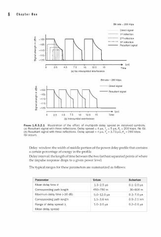
FIGURE 1.6.3.2.1 I l l u s tra i o n of the effect of multi path delay spread on received symbols.
(a) Resultant signal with three reflections. Delay spread = 4 ).lS, T0 = 5 ).lS, R0 = 200 kbps. No lSI.
(b) Resultant signal with three reflections. Delay spread = 4 ).lS, T0 = . 73 ).lS, R0 = 280 kbps.
3
lSI occurs.
Delay window: the width of middle portion of the power delay profile that contains
a certain percentage of energy in the profile.
Delay interval: the length of time between the two farthest separated points of where
the impulse response drops to a given power level.
The typical ranges for these parameters are summarized as follows:
Parameter Urban Suburban
Mean delay time d 1 . 5 - . 5 ).lS 0 . 1 - . 0 ).lS
2
2
Corresponding path length 450-750 m 30-600 m
Maxi u m delay time (-30 dB) 5.0-12.0 ).lS 0.3-7 . 0 ).lS
m
Corresponding path length 1.5-3.6 km 0.9- . 1 km
2
2
Range of delay spread t., 1.0-3.0 ).lS 0.2- . 0 ).lS
Mean delay spread