
Page 33 - Integrated Wireless Propagation Models
P. 33
I n t r o d u c t i o n t o M o d e l i n g M o bi l e S i g n a l s i n W i r e l e s s C o m m u n i c a t i o n s 11
We may calculate their coherence time T c when two signals are arriving at different
times. For example, for a vehicle traveling 60 mph at an 800-MHz carrier, the value of
Tc = 2.5 ms for the analog communication is found from Eq. (1.6.3.5.2). This means that
when the symbol rate is greater than ; = 400 bps, the channel will not cause distortion
c
due to the motion. In a digital transmission system, the coherence time Tc = 7.6 ms is
found from Eq. (1.6.3.5.3). The symbol rate..;- must exceed 132 bps in order to avoid
distortion due to frequency dispersion. c
The two signals are arriving within the coherence time, but distortion could still
occurs due to multipath delay spread if it exceeds symbol duration T,.
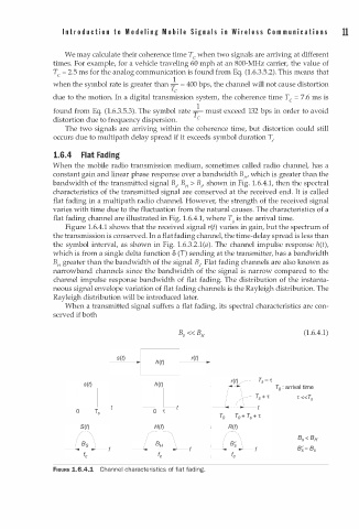
1.6.4 Flat Fading
When the mobile radio transmission medium, sometimes called radio channel, has a
constant gain and linear phase response over a bandwidth Bw which is greater than the
bandwidth of the transmitted signal B,, B > B,, shown in Fig. 1.6.4.1, then the spectral
H
characteristics of the transmitted signal are conserved at the received end. It is called
flat fading in a multipath radio channel. However, the strength of the received signal
varies with time due to the fluctuation from the natural causes. The characteristics of a
flat fading channel are illustrated in Fig. . 6.4.1, where T0 is the arrival time.
1
Figure . 6.4.1 shows that the received signal r(t) varies in gain, but the spectrum of
1
the transmission is conserved. In a flat fading channel, the time-delay spread is less than
1
the symbol interval, as shown in Fig. . 6 .3.2.1(a). The channel impulse response h(t),
which is from a single delta function 8 (T) sending at the transmitter, has a bandwidth
B greater than the bandwidth of the signal B,. Flat fading channels are also known as
H
narrowband channels since the bandwidth of the signal is narrow compared to the
channel impulse response bandwidth of flat fading. The distribution of the instanta
neous signal envelope variation of flat fading channels is the Rayleigh distribution. The
Rayleigh distribution will be introduced later.
When a transmitted signal suffers a flat fading, its spectral characteristics are con
served if both
(1.6.4.1)
__ s� ( t � ) __ ,� L -- --- -- -- '� ( t� ) _
h �
( t )
n n .
0 T s t 0 't
H(f)
�
___L _ _ _ aH _ _ _ L ,
fc
FIGURE 1.6.4.1 Channel characteristics of flat fading.