
Page 37 - Integrated Wireless Propagation Models
P. 37
I n t r o d u c t i o n t o M o d e l i n g M o b i l e S i g n a l s i n W i r e l e s s C o m m u n i c a t i o n s 15
K
=
=
K
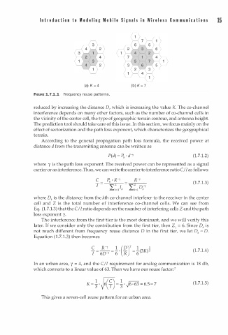
(a) 4 (b) 7
FIGURE 1.7.1.1 Frequency reuse patterns.
reduced by increasing the distance D, which is increasing the value K. The co-channel
interference depends on many other factors, such as the number of co-channel cells in
the vicinity of the center cell, the type of geographic terrain contour, and antenna height.
The prediction tool should take care of this issue. In this section, we focus mainly on the
effect of sectorization and the path loss exponent, which characterizes the geographical
terrain.
According to the general propagation path loss formula, the received power at
distance d from the transmitting antenna can be written as
P(d) = P d-r (1.7.1.2)
0
•
where y is the path loss exponent. The received power can be represented as a signal
carrier or an interference. Thus, we can write the carrier to interference ratio C I I as follows:
c p . R-Y R-Y (1.7.1.3)
0
- - ..,----
z
T � - � z o-r
I
L..k=l k L..k=l k
where Dk is the distance from the kth co-channel interferer to the receiver in the center
cell and Z is the total number of interference co-channel cells. We can see from
.
Eq. (1.7 1 . 3) that the C/I ratio depends on the number of interfering cells Z and the path
loss exponent y.
The interference from the first tier is the most dominant, and we will verify this
later. If we consider only the contribution from the first tier, then Z = 6. Since D is
k
1
not much different from frequency reuse distance D in the first tier, we let D = D .
k
(
Equation 1 . 7 . 1 . 3) then becomes
(1.7.1.4)
In an urban area, y = 4, and the C/I requirement for analog communication is 18 db,
which converts to a linear value of 63. Then we have our reuse factor: 2
6
K = � ·�6(�) =� · � · 6 3 = 6 .5 "' 7 (1.7.1.5)
This gives a seven-cell reuse pattern for an urban area.