
Page 39 - Integrated Wireless Propagation Models
P. 39
t
I n r o d u c t i o n t o M o d e I i n g M o b i I e S i g n a I s i n W i r e I e s s C o m m u n i c a t i o n s 17
i
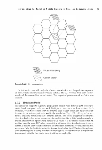
'\ Sector n terfering
� Center sector
FIGURE 1.7.1.2 Cell sectorization.
In this section, we will study the effect of sectorization and the path loss exponent
on the C/I ratio and the frequency reuse factor K. The C/I received from both the for
ward and the reverse link are calculated. The impact of power control on C/I is also
studied.
1 . 7.2 Simulation Model
The simulator supports a general propagation model with different path loss expo
nents. Ideal hexagonal cells are used. Multiple sectors, such as three sectors, Lee's
2
microcell,ZS- 7 and six sectors, with the antenna used in each sector, can be specified by
the user. r eal antenna pattern is used in the simulation (Fig. . 7.2.1). Every cell or sec
A
1
tor has the same parameters (ERP, antenna pattern, and so on) except for the antenna
direction. Each cell or sector has one mobile, and that mobile is distributed randomly in
the cell or sector with a probability density / A, where A is the area of cell or sector. All
1
mobiles have the same ERP when transmitting with omnidirectional antennas if power
control is absent. Each cell or sector uses the same kind of antenna for transmission and
reception. Only the first interfering tier is used to calculate the C!I ratio, although our
simulator is capable of doing multiple interfering tiers. The contribution of higher tiers
is compared with the first tier to show that they are negligible.