
Page 43 - Integrated Wireless Propagation Models
P. 43
I n t r o d u c t i o n t o M o d e l i n g M o b i l e S i g n a l s i n W i r e l e s s C o m m u n i c a t i o n s 21
0 . 1 8
0 . 1 6
0.14
0.12
0.1 -- K = 3
IK
t; 0.08 -- K = 4
_._ K = 7
0.06 - K = 12
0.04
0.02
0
2nd tier 3rd tier 4th tier
FIGURE 1.7.3.4 Forward l i n k path loss exponent y = 4, omni antenna (worst case).
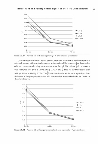
On a reverse link without power control, the worst interference positions for Lee's
microcell system with omni-antennas are at the vertex of the hexagon. For three-sector
cells and six-sector cells, they are at the center of the cell. The ratio of �2 for the omni
cells with path loss y = 4 is shown in Fig. 1.7.3.5. The �2 ratio for the th�ee-sector cells
with y = 4 is shown in Fig. 1.7.3.6. The �2 ratio remains al�ost the same regardless of the
1
difference of frequency reuse factors and sectorized or unsectorized cells, as shown in
these two figures.
0.18
0.16
0.14
0.12
IK 0.1 � K = 3
t;
� K = 4
0.08
-r- K = 7
0.06 """'*"""' K = 1 2
0.04
0.02
0
2nd tier 3rd tier 4th tier
FIGURE 1.7.3.5 Reverse link without power control path loss exponent y = 4, omni-antenna.