
Page 31 - Integrated Wireless Propagation Models
P. 31
I n t r o d u c t i o n t o M o d e l i n g M o bi l e S i g n a l s i n W i r e l e s s C o m m u n i c a t i o n s 9
It is desirable to have the maximum delay spread be small relative to the symbol
interval T = 5 J..lS (also, the data rate is / T = 200 kbps) of a digital communication
1
signal so that the received signal cannot be affected by the delay spread, as shown in
Fig. . 6.3.2.1(a). When the maximum delay spread is greater than the symbol interval,
1
lSI occurs, as shown in Fig. . 6.3.2.1(b). A correlated requirement is that the coherence
1
bandwidth (which is the function of inversed time-delay spread) be greater than the
signal bandwidth. Coherence bandwidth is defined as the bandwidth over which the
channel can be considered flat with linear phase. A flat frequency response with linear
phase implies no signal distortion.
1.6.3.3 Coherence Bandwidth
Coherence bandwidth is a statistical measurement of the range of frequencies over
which the channel can be considered invariant, or "flat." If the signal bandwidth is
less than the coherence bandwidth, B < B,, then the medium channel is considered nar
rowband or flat (flat fading). Otherwise, it is called a wideband channel (frequency
selective fading). Flat fading causes the amplitude of the received signal to vary, but the
spectrum of the signal remains intact. The use of flat fading is to determine the allow
able outage time under the fading and also to use the Rayleigh probability density
function (PDF) to determine the required fade margin to meet the requirement. For
selective fading, some modulations are relatively tolerant of frequency dropouts,
whereas in other cases an equalizer may be used.
One definition of coherence bandwidth is that if the amplitude correlation is at 0.5,
then the coherence bandwidth is approximately 2
1
B e = 2nt., (1.6.3.3.1)
Since an exact relationship between coherence bandwidth and delay spread does
not exist, Eq. (1.6.3.3. ) is a reasonable estimate. In general, spectral analysis techniques
1
are required to realize the exact impact of a time-varying multipath on a particular
2 21
transmitted signal. °·
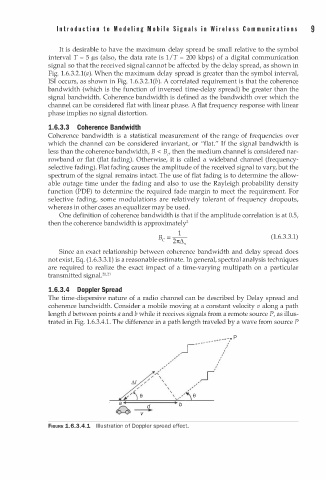
1.6.3.4 Doppler Spread
The time-dispersive nature of a radio channel can be described by Delay spread and
coherence bandwidth. Consider a mobile moving at a constant velocity v along a path
length d between points a and b while it receives signals from a remote source P, as illus
1
trated in Fig. . 6.3.4. . The difference in a path length traveled by a wave from source P
1
s - - -- - -- - - - /.: � p
-
-
-
' ,
/ ,
' ' , I
,' ,
' I
/ '
,<
/ '
/
'
, " '
/ '
/ \
/ / e
\ ,�'
FIGURE 1.6.3.4.1 Illustration of Doppler spread effect.