
Page 402 - Integrated Wireless Propagation Models
P. 402
380 C h a p t e r S i x
required E/No and a planned E/N 0 • The required one is set by the system spec. The
planned one is the one that ensures there is a margin in dB to be added so that under
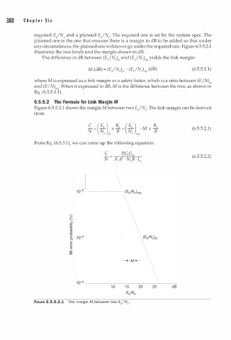
any circumstances, the planned one will never go under the required one. Figure 6.5.5.2.1
illustrates the two levels and the margin shown in dB.
The difference in dB between (E/N) 1 and (E/N),e yields the link margin:
P q
M (dB) = (E/N) 1 - P (E/N)re (dB ) (6.5.5.1.1)
q
where M is expressed as a link margin or a safety factor, which is a ratio between (E!N ) 1
P
and (E/N )re · When it expressed in dB, M is the difference between the two, as shown in
q
Eq. (6.5.5.1.1).
6.5.5.2 The Formula for Link Margin M
Figure 6.5.5.2.1 shows the margin M between two E/ N 0 • The link margin can be derived
from
(6.5.5.2.1)
From Eq. (6.5.3.1), we can come up the following equation:
C �G1G"' (6.5.5.2.2)
N A dY · N B0 · L 0
FIGURE 6.5.5.2.1 The margin M between two Eb/N0 •