
Page 398 - Integrated Wireless Propagation Models
P. 398
376 C h a p t e r S i x
Macro
Tx
*
Micro Tx
� 1 3 1 2 1 1
1 5 1 4 • ... . 1 0 9
1 6 • • . • • 8
1 7 • • Terrain • • 6
7
1 8 contour · • 5 4
•
1 9 . • 3 2
20. • • • 1
•
I
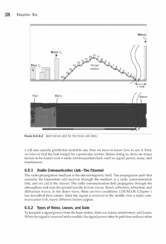
FIGURE 6.4.4.3 Best server plot for the three cell sites.
a cell size-specific prediction model to use, then we have to know how to use it. First,
we have to find the link budget for a particular system. Before doing so, there are many
factors to he found over a radio communication link, such as signal power, noise, and
interference.
6. . 1 Radio Communication Link-The Channel
5
The radio propagation medium is the electromagnetic field. The propagation path that
connects the transmitter and receiver through the medium is a radio communication
link, and we call it the channel. The radio communication link propagates through the
atmosphere and near the ground results in four waves: direct, reflection, refraction, and
diffraction waves. In the direct wave, there are two conditions: LOS NLOS. Chapter 1
has described their nature. After the signal is received at the mobile over a radio com
munication link, many different factors appear.
6.5.2 T y pes of Noise, Losses, and Gain
To transmit a signal power from the base station, there are noises, interference, and losses.
When the signal is received at the mobile, the signal power after its path loss and any other