
Page 66 - Integrated Wireless Propagation Models
P. 66
44 C h a p t e r O n e
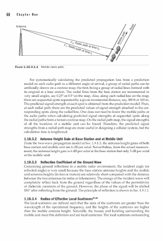
FIGURE 1.10.3.1.1 Mobile radio path.
For systematically calculating the predicted propagation loss from a prediction
model on each radio path in a different angle of arrival, a group of radial paths can be
artificially drawn on a contour map, the first, being a group of radial lines formed with
its original at a base station. The radial lines from the base station are incremented in
very small angles, say 0.25° or 0.5° on the map. Also, along each radial line on the map,
there are sequential spots separated by a given incremental distance, say, 300 ft or 100 m.
The predicted signal strength at each spot is obtained from the prediction model. Then,
at each radial path, there are the predicted values of signal strength attached to the cor
responding spots along the radial line. One does not need to know the mobile paths or
the radio paths when calculating predicted signal strengths at sequential spots along
the radial paths from a terrain contour map. On the radial path map, the signal strengths
of all the locations of a mobile unit can be found. Therefore, the predicted signal
strengths from a radial-path map are more useful in designing a cellular system, but the
calculation time is lengthened.
1.10.3.2 Antenna Height Gain at Base Station and at Mobile Unit
1
From the two-wave propagation model in Sec. . 9.1.3, the antenna height gains of both
base station and mobile unit are 6 dB per octal. Nevertheless, from the actual measure
ment, the antenna height gain is 6 dB per octal at the base station but only 3 dB per octal
at the mobile unit.
1.10.3.3 Reflection Coefficient of the Ground Wave
Concerning ground reflections in a mobile radio environment, the incident angle (or
reflected angle) is very small because the base station antenna heights and the mobile
unit antenna heights (in feet or meters) are relatively short compared with the distance
between the two antennas (in miles or kilometers . The energy of the incident wave will
)
completely reflect back from the ground regardless of the values of the permittivity
of dielectric constants of the ground. However, the phase of the signal will be shifted
180° after reflecting from the ground. The principle of reflection is shown in Sec. . 9 1 . 1 .
1
.
o
1.10.3.4 Radius f Effective Local Scatterers47•48
The local scatterers are defined such that the sizes of the scatterers are greater than the
wavelength of the operational frequency, and the heights of the scatterers are higher
than the mobile antenna height. Naturally, the houses and building surrounding the
mobile unit meet this definition and are local scatterers. The local scatterers surrounding