
Page 62 - Integrated Wireless Propagation Models
P. 62
40 C h a p t e r 0 n e
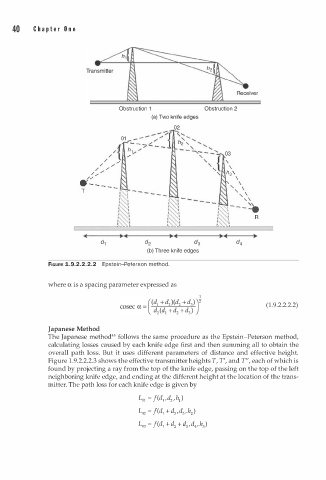
Obstruction 1 Obstruction 2
(a) Two knife edges
02
/
/ {":��;2J 03
/
// .,. "' '\
'\
/ _,. "' / h s'\
/
/;' \
· - - - - - ' ' '\
T ' \
- - , \
, ,
:- - - �
I
\ R
I
- - 1
(b) Three knife edges
FIGURE 1.9.2.2.2.2 Epstein-Peterson method.
where a is a spacing parameter expressed as
(1.9.2.2.2.2)
Japanese Method
The Japanese method45 follows the same procedure as the Epstein-Peterson method,
calculating losses caused by each knife edge first and then summing all to obtain the
overall path loss. But it uses different parameters of distance and effective height.
1
Figure . 9.2.2.2.3 shows the effective transmitter heights T, T', and T", each of which is
found by projecting a ray from the top of the knife edge, passing on the top of the left
neighboring knife edge, and ending at the different height at the location of the trans
mitter. The path loss for each knife edge is given by
LOI = f(d1, d2 , h 1)
=
Loz f(dl + d 2 A , h z )
+
Lo3 = f(dl + d z d 3 , d4, h 3)