
Page 63 - Integrated Wireless Propagation Models
P. 63
I n r o d u c t i o n t o M o d e I i n g M o b i I e S i g n a I s i n W i r e I e s s C o m m u n i c a t i o n s 41
t
T"
FIGURE 1.9.2.2.2.3 Japanese method.
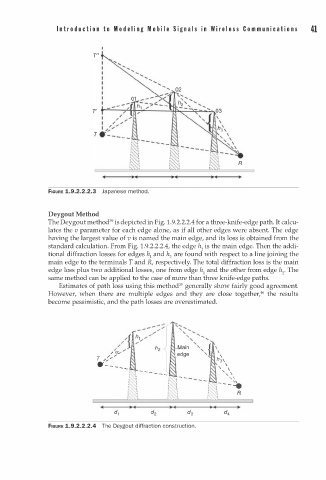
Deygout Method
1
The Deygout method39 is depicted in Fig. . 9.2.2.2.4 for a three-knife-edge path. It calcu
lates the v parameter for each edge alone, as if all other edges were absent. The edge
having the largest value of v is named the main edge, and its loss is obtained from the
standard calculation. From Fig. . 9.2.2.2.4, the edge h 2 is the main edge. Then the addi
1
tional diffraction losses for edges h1 and h are found with respect to a line joining the
3
main edge to the terminals T and R, respectively. The total diffraction loss is the main
edge loss plus two additional losses, one from edge h1 and the other from edge h 2 • The
same method can be applied to the case of more than three knife-edge paths.
Estimates of path loss using this method39 generally show fairly good agreement.
However, when there are multiple edges and they are close together,46 the results
become pessimistic, and the path losses are overestimated.
- - , ....
"
" ex,... edge '._ \
T ,:.- h3,
·- - - .. _ ' , \
: \ - - - - - - ' , ,
: : I � - - - - - - ' �
i \ r 1 : �- - - -e
I I : R
: 't t'
• .. - ... •
• r . . ... '
FIGURE 1.9.2.2.2.4 The Deygout i ffraction construction.
d