
Page 305 - Intelligent Digital Oil And Gas Fields
P. 305
Smart Wells and Techniques for Reservoir Monitoring 253
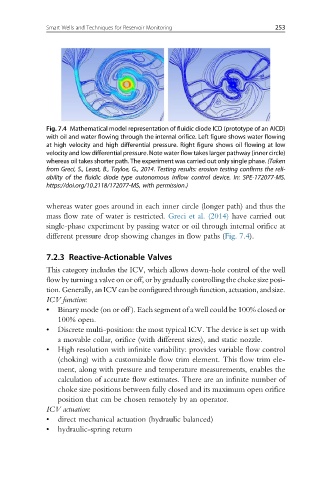
Fig. 7.4 Mathematical model representation of fluidic diode ICD (prototype of an AICD)
with oil and water flowing through the internal orifice. Left figure shows water flowing
at high velocity and high differential pressure. Right figure shows oil flowing at low
velocity and low differential pressure. Note water flow takes larger pathway (inner circle)
whereas oil takes shorter path. The experiment was carried out only single phase. (Taken
from Greci, S., Least, B., Tayloe, G., 2014. Testing results: erosion testing confirms the reli-
ability of the fluidic diode type autonomous inflow control device. In: SPE-172077-MS.
https://doi.org/10.2118/172077-MS, with permission.)
whereas water goes around in each inner circle (longer path) and thus the
mass flow rate of water is restricted. Greci et al. (2014) have carried out
single-phase experiment by passing water or oil through internal orifice at
different pressure drop showing changes in flow paths (Fig. 7.4).
7.2.3 Reactive-Actionable Valves
This category includes the ICV, which allows down-hole control of the well
flow by turning a valve on or off, or by gradually controlling the choke size posi-
tion.Generally,anICV canbe configured throughfunction,actuation, andsize.
ICV function:
• Binary mode (on or off ). Each segment of a well could be 100% closed or
100% open.
• Discrete multi-position: the most typical ICV. The device is set up with
a movable collar, orifice (with different sizes), and static nozzle.
• High resolution with infinite variability: provides variable flow control
(choking) with a customizable flow trim element. This flow trim ele-
ment, along with pressure and temperature measurements, enables the
calculation of accurate flow estimates. There are an infinite number of
choke size positions between fully closed and its maximum open orifice
position that can be chosen remotely by an operator.
ICV actuation:
• direct mechanical actuation (hydraulic balanced)
• hydraulic-spring return