
Page 81 - Intelligent Digital Oil And Gas Fields
P. 81
52 Intelligent Digital Oil and Gas Fields
Not applied to all fluids. Depend on fluid properties, pressure, temperature and separators efficiency
100
Annular
Bubble
Superficial liquid velocity (m/s) 1.0 Plug k = 10 k= 1.0 Wave Mist
10
Slug
0.1
Stratified k= 0.10
0.01
0.01 0.1 1.0 10 100
Superficial gas velocity (m/s)
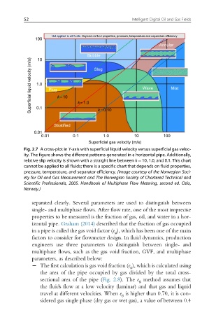
Fig. 2.7 A cross-plot in Y-axis with superficial liquid velocity versus superficial gas veloc-
ity. The figure shows the different patterns generated in a horizontal pipe. Additionally,
relative slip velocity is shown with a straight line between k¼10, 1.0, and 0.1. This chart
cannot be applied to all fluids; there is a specific chart that depends on fluid properties,
pressure, temperature, and separator efficiency. (Image courtesy of the Norwegian Soci-
ety for Oil and Gas Measurement and The Norwegian Society of Chartered Technical and
Scientific Professionals, 2005. Handbook of Multiphase Flow Metering, second ed. Oslo,
Norway.)
separated clearly. Several parameters are used to distinguish between
single- and multiphase flows. After flow rate, one of the most imprecise
properties to be measured is the fraction of gas, oil, and water in a hor-
izontal pipe. Graham (2014) described that the fraction of gas occupied
in a pipe is called the gas void factor (e g ), which has been one of the main
factors to consider for flowmeter design. In fluid dynamics, production
engineers use three parameters to distinguish between single- and
multiphase flows, such as the gas void fraction, GVF, and multiphase
parameters, as described below:
2 The first calculation is gas void fraction (e g ), which is calculated using
the area of the pipe occupied by gas divided by the total cross-
sectional area of the pipe (Fig. 2.8). The e g method assumes that
the fluids flow at a low velocity (laminar) and that gas and liquid
travel at different velocities. When e g is higher than 0.70, it is con-
sidered gas single phase (dry gas or wet gas), a value of between 0.4