
Page 77 - Intelligent Digital Oil And Gas Fields
P. 77
48 Intelligent Digital Oil and Gas Fields
2.1.3.2 Flowmeters: Principles of Measurement
The basic types of meters are based on different measurement principles such
as differential pressure, velocity flow, positive displacement, mass flow, and
elemental analysis (ultrasonic, electromagnetic, thermals, radioactive, etc.).
Differential pressure meter. The most traditional meter used by the oil and
gas (O&G) industry, this meter measures the pressure drop over an orifice
inserted into the flow current. Engineers use the Bernoulli equation to esti-
mate the pressure drop, which is a function of the square flow speed mul-
tiplied by fluid density:
ρ∗v 2
Δp ¼ (2.1)
2
where Δp is the pressure difference measured at the orifice between two
3
points in psi; ρ is the fluid density in lbs/ft , and v is the flow velocity in
ft/s.
The typical devices using this principle are orifice plates, flow nozzles,
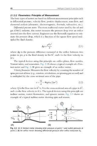
Venturi tubes, and rotameters. Fig. 2.2A shows a typical example of a Ven-
turi meter and Fig. 2.2B gives an example of an orifice meter.
Velocity flowmeter: Measures the flow velocity by counting the number of
spins per unit of time (e.g., rotation, revolutions, or spinning per second) and
is multiplied by the cross-sectional area of the pipe:
Q
v ¼ ¼ #spins= πr 2 (2.2)
A
3
2
where Q is the flow rate in ft /s; A is the cross-sectional area of a pipe in ft ;
and v is the flow velocity in ft/s. The typical devices using this principle are
turbine meters, vortex flowmeters, and spinner meters. Fig. 2.3 shows an
example of a typical turbine meter showing spin and sensors.
P 1 P 2
r 1 r 2
Q
1 D 1 D 0
Flow V 2 2
V 1
(A) (B)
Fig. 2.2 (A) A Venturi meter showing inlet pressure at point 1 and outlet pressure at
point 2. (B) An orifice meter showing differential pressure after orifice reduction D 0 .