
Page 254 - Intro Predictive Maintenance
P. 254
Process Parameters 245
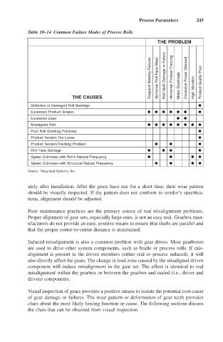
Table 10–14 Common Failure Modes of Process Rolls
THE PROBLEM
Frequent Bearing Failures Abnormal Roll Face Wear Roll Neck Damage or Failure Abnormal Product Tracking Motor Overheats Excessive Power Demand Product Quality Poor
THE CAUSES High Vibration
Defective or Damaged Roll Bearings
Excessive Product Tension
Excessive Load
Misaligned Roll
Poor Roll Grinding Practices
Product Tension Too Loose
Product Tension/Tracking Problem
Roll Face Damage
Speed Coincides with Roll’s Natural Frequency
Speed Coincides with Structural Natural Frequency
Source: Integrated Systems, Inc.
ately after installation. After the gears have run for a short time, their wear pattern
should be visually inspected. If the pattern does not conform to vendor’s specifica-
tions, alignment should be adjusted.
Poor maintenance practices are the primary source of real misalignment problems.
Proper alignment of gear sets, especially large ones, is not an easy task. Gearbox man-
ufacturers do not provide an easy, positive means to ensure that shafts are parallel and
that the proper center-to-center distance is maintained.
Induced misalignment is also a common problem with gear drives. Most gearboxes
are used to drive other system components, such as bridle or process rolls. If mis-
alignment is present in the driven members (either real or process induced), it will
also directly affect the gears. The change in load zone caused by the misaligned driven
component will induce misalignment in the gear set. The effect is identical to real
misalignment within the gearbox or between the gearbox and mated (i.e., driver and
driven) components.
Visual inspection of gears provides a positive means to isolate the potential root-cause
of gear damage or failures. The wear pattern or deformation of gear teeth provides
clues about the most likely forcing function or cause. The following sections discuss
the clues that can be obtained from visual inspection.