
Page 309 - Intro Predictive Maintenance
P. 309
300 An Introduction to Predictive Maintenance
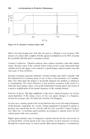
Figure 14–11 Dynamic resonance phase shift.
shift in the time-domain plot. Note that the peak at 1,200rpm is not resonance. The
absence of a phase shift, coupled with the apparent modulations in the FFT, discount
the possibility that this peak is resonance-related.
Common Confusions. Vibration analysts often confuse resonance with other failure
modes. Because many of the common failure modes tend to create abnormally high
vibration levels that appear to be related to a speed change, analysts tend to miss the
root-cause of these problems.
Dynamic resonance generates abnormal vibration profiles that tend to coincide with
the fundamental (1¥) running speed, or one or more of the harmonics, of a machine-
train. This often leads the analyst to incorrectly diagnose the problem as imbalance
or misalignment. The major difference is that dynamic resonance is the result of a
relatively small energy source, such as the fundamental running speed, that results in
a massive amplification of the natural frequency of the rotating element.
Function of Speed. The high amplitudes at the rotor’s natural frequency are strictly
speed dependent. If the energy source, in this case speed, changes to a frequency
outside the resonant zone, the abnormal vibration will disappear.
In most cases, running speed is the forcing function that excites the natural frequency
of the dynamic component. As a result, rotating equipment is designed to operate at
primary rotor speeds that do not coincide with the rotor assembly’s natural frequen-
cies. Most low- to moderate-speed machines are designed to operate below the first
critical speed of the rotor assembly.
Higher-speed machines may be designed to operate between the first and second, or
second and third, critical speeds of the rotor assembly. As these machines accelerate
through the resonant zones or critical speeds, their natural frequency is momentarily