
Page 310 - Intro Predictive Maintenance
P. 310
Failure-Mode Analysis 301
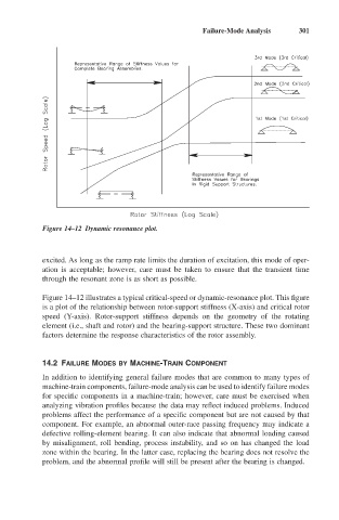
Figure 14–12 Dynamic resonance plot.
excited. As long as the ramp rate limits the duration of excitation, this mode of oper-
ation is acceptable; however, care must be taken to ensure that the transient time
through the resonant zone is as short as possible.
Figure 14–12 illustrates a typical critical-speed or dynamic-resonance plot. This figure
is a plot of the relationship between rotor-support stiffness (X-axis) and critical rotor
speed (Y-axis). Rotor-support stiffness depends on the geometry of the rotating
element (i.e., shaft and rotor) and the bearing-support structure. These two dominant
factors determine the response characteristics of the rotor assembly.
14.2 FAILURE MODES BY MACHINE-TRAIN COMPONENT
In addition to identifying general failure modes that are common to many types of
machine-train components, failure-mode analysis can be used to identify failure modes
for specific components in a machine-train; however, care must be exercised when
analyzing vibration profiles because the data may reflect induced problems. Induced
problems affect the performance of a specific component but are not caused by that
component. For example, an abnormal outer-race passing frequency may indicate a
defective rolling-element bearing. It can also indicate that abnormal loading caused
by misalignment, roll bending, process instability, and so on has changed the load
zone within the bearing. In the latter case, replacing the bearing does not resolve the
problem, and the abnormal profile will still be present after the bearing is changed.