
Page 173 - Intro to Space Sciences Spacecraft Applications
P. 173
160 Introduction to Space Sciences and Spacecraft Applications
three of these range spheres (once again, knowing precisely the position
of the transmitter[s]).
The concept is quite simple, but actual implementation of the idea
poses some real problems. For example, the signal sent by the satellite,
from which the observer will compute range, must allow the receiver to
determine exactly when a particular event was transmitted.
Ranging Signal
Specifying the particular “event” to be used to compute range lends
itself very well to digital techniques. To determine exactly which “event”
has been received (assuming the satellite transmits continuously), a digi-
tal code with a unique pattern could be used. The receiver picks up the sig-
nal and compares it to the same code stored in memory to find where
along the pattern the received information is located.
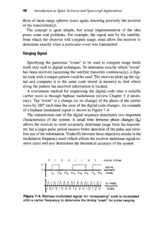
A convenient method for impressing the digital code onto a suitable
carrier wave is through biphase modulation (review Chapter 5 if neces-
sary). The “event” is a change (or no change) of the phase of the carrier
wave by 180” each time the mate of the digital code changes. An example
of a biphase modulated signal is shown in Figure 7-4.
The transmission rate of the digital sequence determines two important
characteristics of the system. A small time between phase changes (Q
allows the receiver to more accurately determine range from the transmit-
ter, but a larger pulse period ensures better detection of the pulse and error-
free use of the information. Tradeoffs between these objectives results in the
modulation frequency used (which affects the receiver minimum signal-to-
noise ratio) and also determines the theoretical accuracy of the system.
0 1 0 0 1 1 0 1 ’.. DIGITAL STRING
”BED
BI - PHASE
MODULATED
SIGNAL
Figure 7-4. Biphase modulated signal. An “unrepeating” code is modulated
onto a carrier frequency to determine the timing “mark” for pulse ranging.