
Page 174 - Intro to Space Sciences Spacecraft Applications
P. 174
Satellite Navigation 161
Timing Signal
Another difficulty posed by the ranging concept is determining exactly
when the particular “event” was sent. Solving this problem involves two
steps: correlation and synchronization.
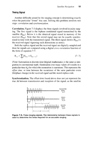
Correlation. Figure 7-5 displays the three signals involved in pulse rang-
ing. The first signal is the biphase modulated signal transmitted by the
satellite Below it is the identical signal stored in memory of the
receiver (SI($. Note that this stored signal may not be exactly synchro-
nized in time with the transmitted signal. The third signal shown (S2(t)) is
the received signal (ignoring such distractions as noise).
Both the replica signal and the received signal are digitally sampled and
then the signals are compared using a digital cross correlation function of
the form of equation 7-7:
t
(Note: Summation in discrete-time [digital] mathematics is the same as inte-
gration in conventional math.) Summation over many values oft results in a
particular time (to) for which the summation is maximum. This represents the
offset time, or time between the occurrence of the same particular event
(bitlphase change) in the received signal and the stored replica code.
Synchronization. The offset time found above does not yet represent the
true At between transmission and reception of the signal, as the satellite
Figure 7-5. Pulse ranging signals. The relationship between these signals is
used to determine the times required for an accurate ranging.