
Page 250 - Introduction to AI Robotics
P. 250
6.7 Range from Vision
θ θ 233
θ 1 θ 2 1 2
baseline
a. b.
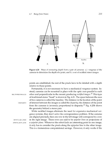
Figure 6.20 Ways of extracting depth from a pair of cameras: a.) vergence of the
cameras to determine the depth of a point, and b.) a set of rectified stereo images.
points are established, the rest of the pixels have to be labeled with a depth
relative to those points.
Fortunately, it is not necessary to have a mechanical vergence system. In-
stead, cameras can be mounted in place with the optic axes parallel to each
RECTIFIED IMAGES other and perpendicular to the mount, producing rectified images. 41 This type
of traditional stereo “head” is shown in Fig. 6.21. The space between the axes
of two cameras is called the baseline. The distance in the location of the point
DISPARITY of interest between the images is called the disparity; the distance of the point
from the cameras is inversely proportional to disparity. 69 Fig. 6.20b shows
the geometry behind a stereo pair.
While rectified images eliminate the need for expensive mechanical ver-
gence systems, they don’t solve the correspondence problem. If the cameras
are aligned precisely, then one row in the left image will correspond to a row
EPIPOLAR LINES in the right image. These rows are said to be epipolar lines or projections of
EPIPOLAR PLANE a epipolar plane. Whenever the robot finds an interesting point in one image,
it only has to consider the pixels along the epipolar line in the other image.
This is a tremendous computational savings. However, it only works if the