
Page 251 - Introduction to AI Robotics
P. 251
234
6 Common Sensing Techniques for Reactive Robots
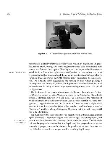
Figure 6.21 A stereo camera pair mounted on a pan/tilt head.
cameras are perfectly matched optically and remain in alignment. In prac-
tice, robots move, bump, and suffer alignment drifts, plus the cameras may
have some flaws in their optics. The alignment can be periodically compen-
CAMERA CALIBRATION sated for in software through a camera calibration process, where the robot
is presented with a standard and then creates a calibration look up table or
function. Fig. 6.22 shows the CMU Uranus robot calibrating its camera sys-
tem. As a result, many researchers are turning to units which package a
stereo pair in one fixed case, where the alignment cannot be altered. Fig. 6.25
shows the results using a stereo range system using three cameras in a fixed
configuration.
The first robot to use stereo vision successfully was Hans Moravec’s Stan-
ford Cart shown in Fig. 6.23a Moravec worked on the Cart while at graduate
school at Stanford between 1973 and 1980. Fig. 6.23b shows the Marsokhod
rover developed in the late 1990’s which used a stereo pair for real-time nav-
igation. Longer baselines tend to be more accurate because a slight mea-
surement error has a smaller impact, but smaller baselines have a smaller
“footprint,” in effect, take up less room. The same point in both images still
has to be identified.
Fig. 6.24 shows the simplified flow of operations in extracting range from
a pair of images. The process begins with two images, the left-right pair, and
RANGE IMAGE results in a third image called the range image or the depth map. The left-right
DEPTH MAP pair can be grayscale or color, but the depth map is a grayscale map, where
intensity is proportional to the distance the pixel is away from the cameras.
Fig. 6.25 shows two stereo images and the resulting depth map.