
Page 129 - Introduction to Autonomous Mobile Robots
P. 129
114
a) b Chapter 4
u
fcotα-u
Camera
Laser / Collimated beam
u
b f
x
α Lens
H=D·tanα
z
b)
Target
(x, z)
Transmitted Beam
c) Reflected Beam
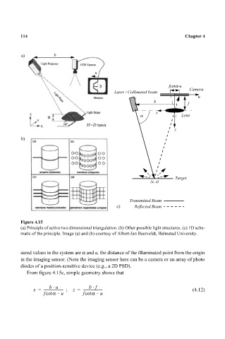
Figure 4.15
(a) Principle of active two dimensional triangulation. (b) Other possible light structures. (c) 1D sche-
matic of the principle. Image (a) and (b) courtesy of Albert-Jan Baerveldt, Halmstad University.
sured values in the system are α and u, the distance of the illuminated point from the origin
in the imaging sensor. (Note the imaging sensor here can be a camera or an array of photo
diodes of a position-sensitive device (e.g., a 2D PSD).
From figure 4.15c, simple geometry shows that
⋅
⋅
bu bf
x = ----------------------- ; z = ----------------------- (4.12)
fcot α – u fcot α – u