
Page 124 - Introduction to Autonomous Mobile Robots
P. 124
Perception
D 109
Transmitter
P
L Target
Phase Transmitted Beam
Measurement Reflected Beam
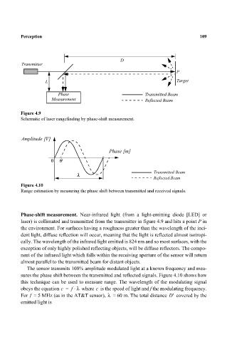
Figure 4.9
Schematic of laser rangefinding by phase-shift measurement.
Amplitude [V]
Phase [m]
0 θ
λ Transmitted Beam
Reflected Beam
Figure 4.10
Range estimation by measuring the phase shift between transmitted and received signals.
Phase-shift measurement. Near-infrared light (from a light-emitting diode [LED] or
laser) is collimated and transmitted from the transmitter in figure 4.9 and hits a point P in
the environment. For surfaces having a roughness greater than the wavelength of the inci-
dent light, diffuse reflection will occur, meaning that the light is reflected almost isotropi-
cally. The wavelength of the infrared light emitted is 824 nm and so most surfaces, with the
exception of only highly polished reflecting objects, will be diffuse reflectors. The compo-
nent of the infrared light which falls within the receiving aperture of the sensor will return
almost parallel to the transmitted beam for distant objects.
The sensor transmits 100% amplitude modulated light at a known frequency and mea-
sures the phase shift between the transmitted and reflected signals. Figure 4.10 shows how
this technique can be used to measure range. The wavelength of the modulating signal
⋅
c
obeys the equation c = f λ where is the speed of light and f the modulating frequency.
λ
For = 5 MHz (as in the AT&T sensor), = 60 m. The total distance D' covered by the
f
emitted light is