
Page 125 - Introduction to Autonomous Mobile Robots
P. 125
110
a) b) Chapter 4
Reflected light
Rotating Transmitted light c)
Mirror
Reflected light
LED/Laser
Detector
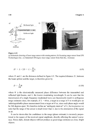
Figure 4.11
(a) Schematic drawing of laser range sensor with rotating mirror; (b) Scanning range sensor from EPS
Technologies Inc.; (c) Industrial 180 degree laser range sensor from Sick Inc., Germany
θ
D' = L + 2D = L + ------λ (4.9)
2π
L
where D and are the distances defined in figure 4.9. The required distance D , between
the beam splitter and the target, is therefore given by
λ
D = ------θ (4.10)
4π
where θ is the electronically measured phase difference between the transmitted and
λ
reflected light beams, and the known modulating wavelength. It can be seen that the
transmission of a single frequency modulated wave can theoretically result in ambiguous
λ
range estimates since, for example, if = 60 m, a target at a range of 5 m would give an
indistinguishable phase measurement from a target at 65 m, since each phase angle would
λ
be 360 degrees apart. We therefore define an “ambiguity interval” of , but in practice we
λ
note that the range of the sensor is much lower than due to the attenuation of the signal
in air.
It can be shown that the confidence in the range (phase estimate) is inversely propor-
tional to the square of the received signal amplitude, directly affecting the sensor’s accu-
racy. Hence dark, distant objects will not produce as good range estimates as close, bright
objects.