
Page 54 - Introduction to Autonomous Mobile Robots
P. 54
Locomotion
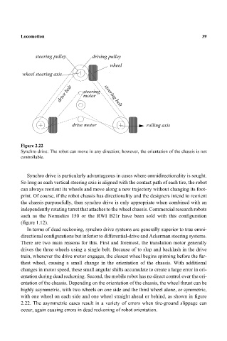
steering pulley driving pulley 39
wheel
wheel steering axis
drive belt steering steering belt
motor
drive motor rolling axis
Figure 2.22
Synchro drive: The robot can move in any direction; however, the orientation of the chassis is not
controllable.
Synchro drive is particularly advantageous in cases where omnidirectionality is sought.
So long as each vertical steering axis is aligned with the contact path of each tire, the robot
can always reorient its wheels and move along a new trajectory without changing its foot-
print. Of course, if the robot chassis has directionality and the designers intend to reorient
the chassis purposefully, then synchro drive is only appropriate when combined with an
independently rotating turret that attaches to the wheel chassis. Commercial research robots
such as the Nomadics 150 or the RWI B21r have been sold with this configuration
(figure 1.12).
In terms of dead reckoning, synchro drive systems are generally superior to true omni-
directional configurations but inferior to differential-drive and Ackerman steering systems.
There are two main reasons for this. First and foremost, the translation motor generally
drives the three wheels using a single belt. Because of to slop and backlash in the drive
train, whenever the drive motor engages, the closest wheel begins spinning before the fur-
thest wheel, causing a small change in the orientation of the chassis. With additional
changes in motor speed, these small angular shifts accumulate to create a large error in ori-
entation during dead reckoning. Second, the mobile robot has no direct control over the ori-
entation of the chassis. Depending on the orientation of the chassis, the wheel thrust can be
highly asymmetric, with two wheels on one side and the third wheel alone, or symmetric,
with one wheel on each side and one wheel straight ahead or behind, as shown in figure
2.22. The asymmetric cases result in a variety of errors when tire-ground slippage can
occur, again causing errors in dead reckoning of robot orientation.