
Page 64 - Introduction to Autonomous Mobile Robots
P. 64
Mobile Robot Kinematics
Y I 49
Y R
X R
θ
P
X I
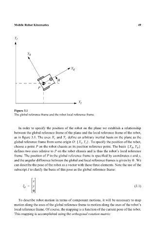
Figure 3.1
The global reference frame and the robot local reference frame.
In order to specify the position of the robot on the plane we establish a relationship
between the global reference frame of the plane and the local reference frame of the robot,
as in figure 3.1. The axes X I and Y I define an arbitrary inertial basis on the plane as the
global reference frame from some origin O: X Y,{ I I } . To specify the position of the robot,
choose a point P on the robot chassis as its position reference point. The basis X Y,{ R R }
defines two axes relative to P on the robot chassis and is thus the robot’s local reference
frame. The position of P in the global reference frame is specified by coordinates x and y,
θ
and the angular difference between the global and local reference frames is given by . We
can describe the pose of the robot as a vector with these three elements. Note the use of the
subscript I to clarify the basis of this pose as the global reference frame:
x
ξ = y (3.1)
I
θ
To describe robot motion in terms of component motions, it will be necessary to map
motion along the axes of the global reference frame to motion along the axes of the robot’s
local reference frame. Of course, the mapping is a function of the current pose of the robot.
This mapping is accomplished using the orthogonal rotation matrix: