
Page 73 - Introduction to Autonomous Mobile Robots
P. 73
58
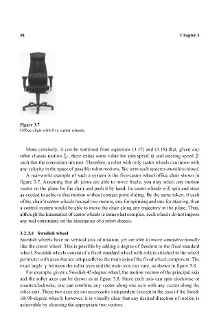
Figure 3.7 Chapter 3
Office chair with five castor wheels.
More concisely, it can be surmised from equations (3.17) and (3.18) that, given any
· · ·
robot chassis motion ξ I , there exists some value for spin speed ϕ and steering speed β
such that the constraints are met. Therefore, a robot with only castor wheels can move with
any velocity in the space of possible robot motions. We term such systems omnidirectional.
A real-world example of such a system is the five-castor wheel office chair shown in
figure 3.7. Assuming that all joints are able to move freely, you may select any motion
vector on the plane for the chair and push it by hand. Its castor wheels will spin and steer
as needed to achieve that motion without contact point sliding. By the same token, if each
of the chair’s castor wheels housed two motors, one for spinning and one for steering, then
a control system would be able to move the chair along any trajectory in the plane. Thus,
although the kinematics of castor wheels is somewhat complex, such wheels do not impose
any real constraints on the kinematics of a robot chassis.
3.2.3.4 Swedish wheel
Swedish wheels have no vertical axis of rotation, yet are able to move omnidirectionally
like the castor wheel. This is possible by adding a degree of freedom to the fixed standard
wheel. Swedish wheels consist of a fixed standard wheel with rollers attached to the wheel
perimeter with axes that are antiparallel to the main axis of the fixed wheel component. The
γ
exact angle between the roller axes and the main axis can vary, as shown in figure 3.8.
For example, given a Swedish 45-degree wheel, the motion vectors of the principal axis
and the roller axes can be drawn as in figure 3.8. Since each axis can spin clockwise or
counterclockwise, one can combine any vector along one axis with any vector along the
other axis. These two axes are not necessarily independent (except in the case of the Swed-
ish 90-degree wheel); however, it is visually clear that any desired direction of motion is
achievable by choosing the appropriate two vectors.