
Page 74 - Introduction to Autonomous Mobile Robots
P. 74
Mobile Robot Kinematics
Y R 59
β
γ
ϕ, r
Robot chassis
l A
α
X
P R
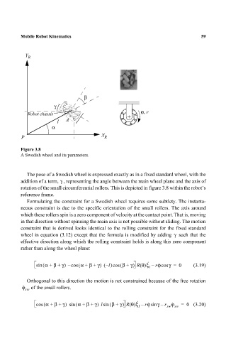
Figure 3.8
A Swedish wheel and its parameters.
The pose of a Swedish wheel is expressed exactly as in a fixed standard wheel, with the
γ
addition of a term, , representing the angle between the main wheel plane and the axis of
rotation of the small circumferential rollers. This is depicted in figure 3.8 within the robot’s
reference frame.
Formulating the constraint for a Swedish wheel requires some subtlety. The instanta-
neous constraint is due to the specific orientation of the small rollers. The axis around
which these rollers spin is a zero component of velocity at the contact point. That is, moving
in that direction without spinning the main axis is not possible without sliding. The motion
constraint that is derived looks identical to the rolling constraint for the fixed standard
γ
wheel in equation (3.12) except that the formula is modified by adding such that the
effective direction along which the rolling constraint holds is along this zero component
rather than along the wheel plane:
·
·
l
sin ( α + β + γ) – cos ( α + β + γ) –()cos ( β + γ) R θ()ξ – rϕcos γ = 0 (3.19)
I
Orthogonal to this direction the motion is not constrained because of the free rotation
ϕ · sw of the small rollers.
·
γ
·
cos ( α + β + γ) sin ( α + β + γ) lsin ( β + γ) R θ()ξ – rϕsin – r ϕ · = 0 (3.20)
I sw sw