
Page 28 - Introduction to Computational Fluid Dynamics
P. 28
P2: IWV
P1: JYD/GKJ
CB908/Date
0 521 85326 5
0521853265c01
1.4 MAIN TASK
WALL May 20, 2005 12:20 7
AIR INFLOW EXIT
LIP WALL
FUEL INFLOW
SYMMETRY
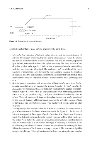
Figure 1.1. Typical two-dimensional domain.
combustion chamber of a gas-turbine engine will be considered.
1. Given the flow situation of interest, define the physical (or space) domain of
interest. In unsteady problems, the time domain is imagined. Figure 1.1 shows
the domain of interest of the idealised chember. Fuel and air streams, separated
by a lip wall, enter the chamber at the inflow boundary. The cross section of the
chamber is taken to be a perfect circle so that a symmetry boundary coinciding
with the axis is readily identified. The enclosing wall is solid and the burnt
products of combustion leave through the exit boundary. Because the situation
is idealised as a two-dimensional axisymmetric domain that will involve fluid
recirculation, there are four boundaries of interest: inflow, wall, symmetry, and
exit.
2. Select transport equations with appropriate diffusion and source laws. Define
boundary conditions on segments of the domain boundary for each variable .
Also, define the fluid properties. The boundary segments have already been iden-
tified in Figure 1.1. Now, since air and fuel mix and react chemically, equations
for = u 1 , u 2 , u 3 (swirl velocity), T or h, and several mass fractions ω k must be
solved. The choice of ω k will of course depend on the reaction model postulated
by the analyst. Further, additional equations must be solved to capture effects
of turbulence via a turbulence model. This matter will become clear in later
chapters.
3. Select points (called nodes) within the domain so as to map the domain with a
grid. Construct control volumes around each node. In Figure 1.2, the domain of
interest is mapped by three types of grids: Cartesian, Curvilinear, and Unstruc-
tured. The hatched portions show the control volumes and the filled circles are
the nodes. Note that in the Cartesian grids, the control volumes near the slanted
wall are not rectangular as elsewhere. This type of difficulty is overcome in the
curvilinear grids where all control volumes are quadrilaterals and the grid lines
follow the contours of the domain boundary as required. The unstructured grid is
completely arbitrary. Although most control volumes are triangular, one can also