
Page 194 - Introduction to Information Optics
P. 194
3.2. Light Propagation in Optical Fibers
can be expressed as
E s(p) = e-*<"\ W = a o.65 + + , (336)
which is basically Guassian function. To understand Eqs. (3.35) and (3.36), let
us look at the following example.
Example 3.7. A single mode silica fiber has a radius a = 2.6 ^m, core refractive
index n^ — 1.465, the cladding refractive index n 2 — 1-45, and operating
wavelength A = 1.55 /mi.
(a) Draw the transversal electric field distribution E z(p) for both exact
formular (i.e., Eq. [3.35]) and empirical Gaussian approximation formu-
lar (i.e., Eq. [3.36]).
(b) Redo part (a) if the fiber radius is changed to a = 1.2 /an.
Solve: (a) First, the parameters in Eqs. (3.35) and (3.36) are calculated. In case
(a), the normalized frequency is
2n 2n , 1
= 4.054 junT ,
x 1.55/im
1.55 /on v
The propagation constant, /?, is calculated using the graphic approach as
described in Example (3.6). It is found that /? — 5.907. Then, the parameters K
and y are calculated:
2
2
2
K = x/nf^ - ff- = x/1.465 -4.054 - 5.907 - 0.825.
Similarly, we get
0.586.
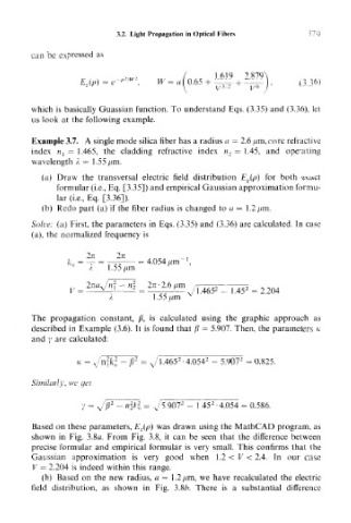
Based on these parameters, E z(p) was drawn using the MathCAD program, as
shown in Fig. 3.8a. From Fig. 3.8, it can be seen that the difference between
precise formular and empirical formular is very small. This confirms that the
Gaussian approximation is very good when 1.2 < V < 2.4. In our case
V = 2.204 is indeed within this range.
(b) Based on the new radius, a = 1 .2 /xm, we have recalculated the electric
field distribution, as shown in Fig. 3.8/>. There is a substantial difference