
Page 192 - Introduction to Information Optics
P. 192
3.2. Light Propagation in Optical Fibers
Preform
Furnace
Diameter
i i n r~y monitor
Ji-, Coater for jacket
Drawing
tractors
Tensile-strength
monitor
Winding
• | drum
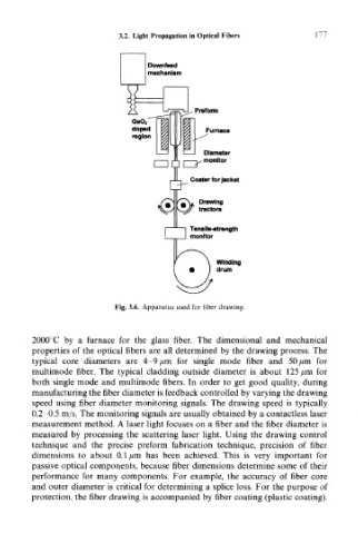
Fig. 3.6. Apparatus used for fiber drawing.
2000°C by a furnace for the glass fiber. The dimensional and mechanical
properties of the optical fibers are all determined by the drawing process. The
typical core diameters are 4-9 jum for single mode fiber and 50 /mi for
multimode fiber. The typical cladding outside diameter is about 125 /mi for
both single mode and multimode fibers. In order to get good quality, during
manufacturing the fiber diameter is feedback controlled by varying the drawing
speed using fiber diameter monitoring signals. The drawing speed is typically
0.2-0.5 m/s. The monitoring signals are usually obtained by a contactless laser
measurement method. A laser light focuses on a fiber and the fiber diameter is
measured by processing the scattering laser light. Using the drawing control
technique and the precise preform fabrication technique, precision of fiber
dimensions to about 0.1 ^.m has been achieved. This is very important for
passive optical components, because fiber dimensions determine some of their
performance for many components. For example, the accuracy of fiber core
and outer diameter is critical for determining a splice loss. For the purpose of
protection, the fiber drawing is accompanied by fiber coating (plastic coating).