
Page 230 - Introduction to Information Optics
P. 230
4.2. All-Optical Switches 2 1 5
4.2.4.2. NOLM with External Control
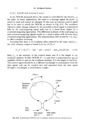
In the NOLM discussed above, the output is controlled by the intensity of
the input. In many applications, the input is a message signal the power of
which is weak and cannot be changed. In this case an external control signal
has to be used to switch the NOLM, as shown in Fig. 4.12. The nonlinear
refractive index change induced by the powerful control signal is experienced
fully by the copropagating signal pulse but to a much lesser degree by a
counterpropagating signal pulse. This difference in phases of the copropagating
and counterpropagating signals results in a relative phase shift between these
counterpropagating signal pulses. The induced phase shift should be n in order
to effect complete switching.
Assuming that there is no nonlinear effect induced by the input signal £ in ,
the total intensity output is found from Eq. (4.23) as
4)0 + cos[(l - 2q)I ea2nn 2D/X])}. (4.26)
Here / ext is the intensity of the control beam, and D is the length of the
nonlinear medium. In fiber NOLM, D = L, and when a semiconductor optical
amplifier (SOA) is used as the nonlinear medium, D is the length of the SOA.
The control signal should be at a different wavelength or polarization from the
data signal, and can be coupled into and separated from the data signal
through a wavelength or polarization coupler.
Offset x
Control
out
Nonlinear
Element
(SOA)
Coupler
Data
input
Data output Data output
(port 1) (port 2)
Fig. 4.12. Asymmetrical NOLM with a nonlinear element and an external control.